What is a 13.56MHz PCB Antenna Embedded RFID/NFC Antenna?
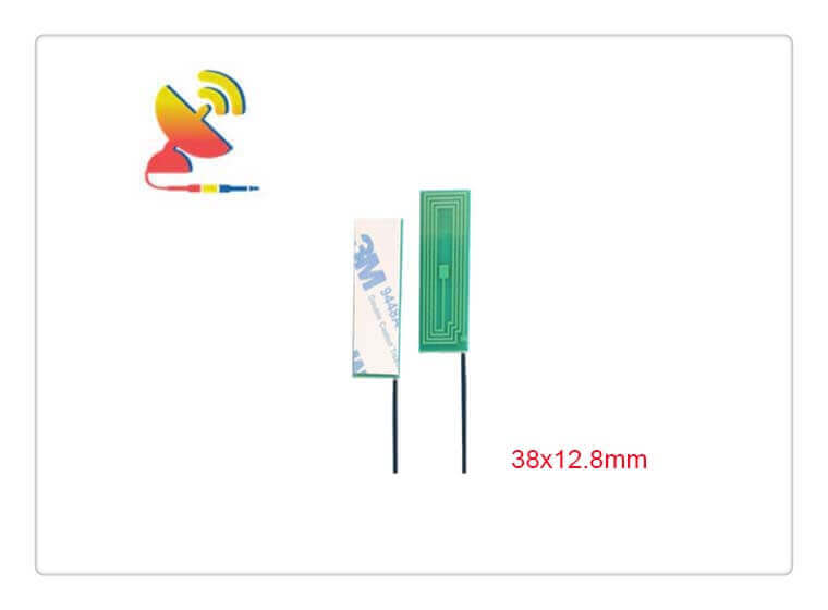
The 13.56MHz PCB Antenna Embedded RFID/NFC Antenna CTRF-ANTENNA-PCB-1356-3813-IPEX antenna is an embedded PCB Antenna NFC 13.56 MHz antenna manufactured by C&T RF Antennas Inc for RFID/NFC wireless network applications.
The 13.56MHz PCB Antenna Embedded RFID/NFC Antenna has a small PCB size of 38×12.8mm, a 1dBi gain, and an Ipex/u.FL connector, indoor antenna for RFID/NFC applications.
C&T RF Antennas Inc, the IoT & M2M antenna internal-external antennas manufacturer in China, manufactures High-performance Low-profile GSM LTE Aerial PCB Antennas.
C&T RF Antennas Inc provides antenna types such as Through-hole Mount Antennas, Magnetic Mount Antennas, Rubber Duck Antennas, Fiberglass Antennas, PCB Antennas, FPC Antennas, Spring Coil Antennas, Sector Antennas, Yagi antennas, etc.
C&T RF Antennas Inc provides the internal-external IoT & M2M antenna with many radio frequency bands such as Cellular, 6G, 5G, 4G, 3G, NB-IoT, GNSS, GPS, Dual-band Wifi, 5.8 GHz, 2.4 GHz, 169MHz, 230MHz, 315MHz, 433MHz, 868MHz, 915MHz LoRa, UWB, RFID, ADS-B, etc.
C&T RF Antennas Inc provides single-band, dual-band, and multi-band antennas for Wi-Fi And Bluetooth, GPS And GNSS, LoRa And ISM, IoT, And M2M applications.
Contact us for details on the 13.56MHz PCB Antenna Embedded RFID/NFC Antenna, such as the 13.56MHz PCB Antenna datasheet, 13.56MHz PCB Antenna pricing, 13.56MHz PCB Antenna inventory, etc.
Or the other internal & external RFID Antenna types.
High-performance Low-profile 13.56MHz PCB Antenna Embedded RFID/NFC Antenna Specifications
13.56MHz PCB Antenna Embedded RFID/NFC Antenna Electrical Specifications | |
| RF Antenna Type | Built-in PCB Antenna |
| Model | CTRF-ANTENNA-PCB-3208-8221-IPEX |
| Frequency Range | 13.56 MHz |
| Gain | 1±0.2dBi |
| Radiation Pattern | Omnidirectional |
| VSWR | ≤2.0 |
| Impedance | 50 Ω |
| Polarization | Vertical Polarization |
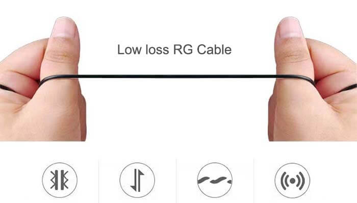
| Cable Type | RG1.13 |
| Cable Length | 100mm |
| Connector | U.FL/IPEX |
| Lightning Protection | DC-Ground |
13.56MHz PCB Antenna Embedded RFID/NFC Antenna Mechanical Specifications | |
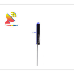
| PCB Board Dimension | 38*12.8mm |
| Weight | Approx. 5g |
| Material | PCB |
| Operation Temperature | -40˚C ~ +85˚C |
| Storage Temperature | -40˚C ~ +80˚C |
| Color | Green |
| Antenna Design | Dipole Array |
| Connector Pull Test | >= 1 Kg |
| SafetyEmission and other | RoHS Compliant |
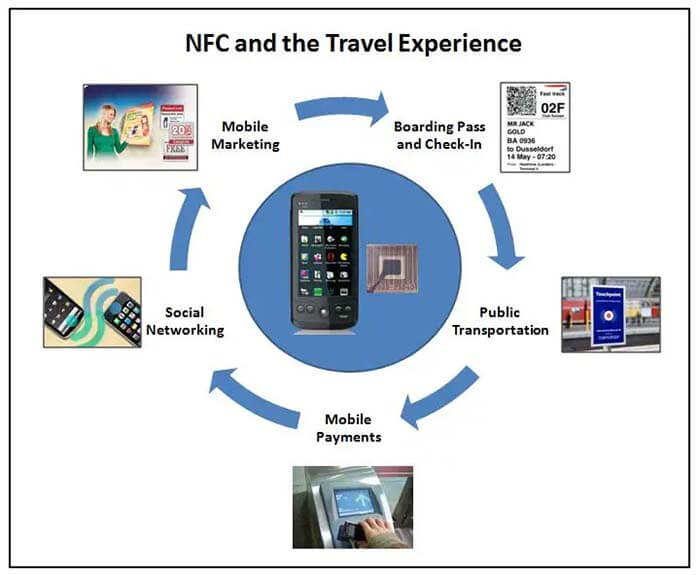
| Applications | ISM/IoT/LoRa/RFID/NFC |
What is the 13.56 MHz in RFID?
13.56MHz (megahertz) and 2.4GHz (hertz) are the same as the frequency of wireless devices, like cordless phones, wire-free frequency transmission, and reception frequency is generally 2.4GHz, 13.56MHz can generally be used for radio frequency identification.
Radiofrequency identification technology (RFID) according to its use of different frequencies can be divided into low-frequency, high-frequency, and ultra-high-frequency systems, different frequency bands of RFID products will have different characteristics. And 13.56MHz belongs to the high-frequency range.
High-frequency characteristics and applications:
At this frequency, the inductor no longer needs a coil for winding, and the antenna can be made by etching or printing. The inductors generally operate by means of load modulation.
Through the inductor on the load resistance of the connection and disconnection to promote the read-write antenna on the voltage change, realize with the long-distance inductor to the antenna voltage amplitude modulation.
If one controls the load voltage connection and disconnection through the data, then these data can be transmitted from the inductor to the reader.
13.56 MHz RFID Characteristics:
1. The operating frequency is 13.56MHz and the wavelength of this frequency is approximately 22MHz.
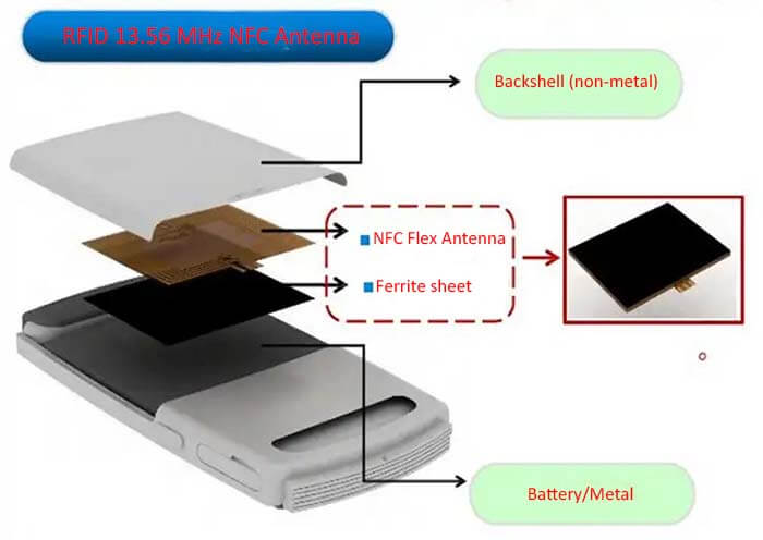
2. The wavelength of this frequency can pass through most materials, except metal, but it tends to reduce the reading distance. The sensor needs to be kept some distance away from the metal.
3. The frequency band is recognized worldwide and has no special restrictions.
4. The sensors are generally in the form of electronic tags.
5. Although the magnetic field area of this frequency drops quickly, it can produce a relatively uniform read/write area. 6.
6. The system has anti-collision characteristics and can read multiple electronic tags at the same time.
7. Certain data information can be written into the tag.
8. The data transmission rate is faster than the low frequency, and the price is not very expensive.
13.56 MHz RFID international standards met:
a) ISO/IEC 14443 proximity-coupled IC cards, with a maximum reading distance of 10cm.
b) ISO/IEC 15693 Sparsely coupled IC cards, with a maximum reading distance of 1m.
c) ISO/IEC 18000-3 This standard defines the physical layer, anti-collision algorithms, and communication protocols for 13.56MHz systems.
d) 13.56MHz ISM Band Class 1 Defines the interface definition for 13.56MHz compliant EPC.
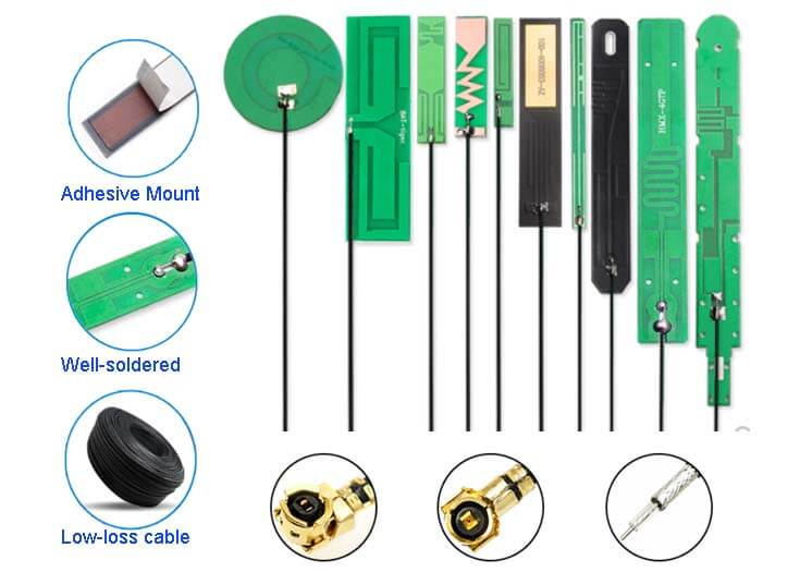
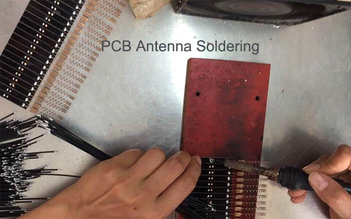
High-performance PCB Antenna features
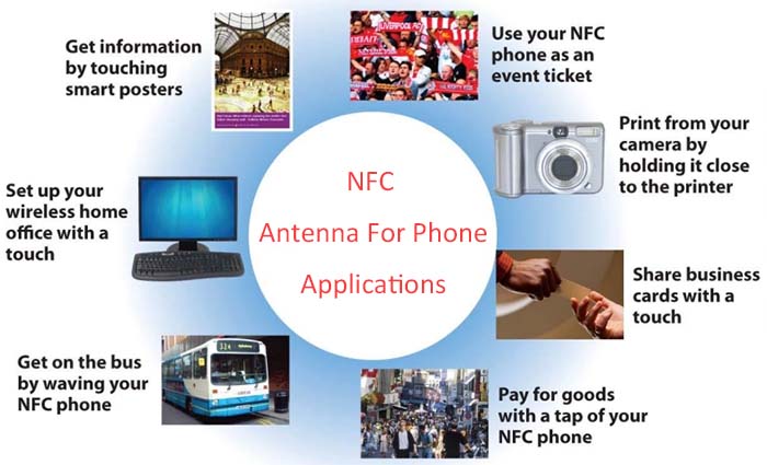
High-performance RFID/NFC Antenna Applications

Reviews
There are no reviews yet.