What Are The Common Types of Antennas?
What are the common types of antennas? How to choose the right types of antennas for the devices? The types of antennas classification The antenna is
Changan, Dongguan, 523863
24/7 Customer Support
Online support always open
The antenna is an important component required by all kinds of smart devices, and all devices that need to use wireless need to use it. Now is the wireless era, network routers are all wireless Wi-Fi, computers, mobile phones are connected to the network no longer need to connect with a network cable, and there are no more wires for Bluetooth headsets, Bluetooth mice, Bluetooth keyboards, etc. The performance of this antenna is very important.
Generally, there are some factors in the selection of antennas, in addition to considering the performance, but also considering the cost, so when selecting the antenna, you need to consider comprehensively.
Antennas generally have the following types.
This kind of antenna has a low cost, but its performance will be slightly worse. There are also several forms of PCB board antennas.
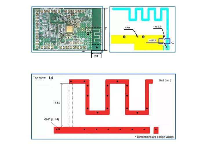
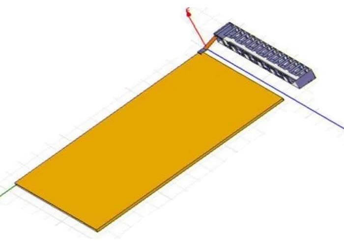
As shown in Figure 1 is the PCB antenna design of inverted F PIFA antenna
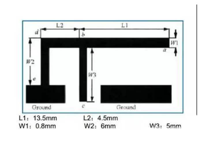
We must first know this knowledge of radiofrequency. For radiofrequency, any copper foil or wire cannot be regarded as a simple wire. It is an equivalent circuit composed of many resistance-capacitance circuits. If you see a short circuit, it is not a short circuit for radiofrequency. With this idea, let’s take a look at the PCB design of this inverted F antenna PIFA antenna.
There are six points to pay attention to in the PCB design of the PIFA antenna.
The PIFA antenna on the mobile phone is called a planar inverted F antenna. In principle, a plane is connected to a ground plane feed point to form an RF feed point. It is also a PIFA antenna with an inverted F structure, but the antenna in the mobile phone uses a planar structure. This planar inverted F antenna has a much better performance than the PCB antenna, so it has less space and low cost, which is the best choice for mobile phone antennas.
In fact, this plane has many shapes for different mobile phones. The principle is a planar inverted-F structure PIFA antenna. On this plane, one is connected to RF and the other is a grounded feed point to form a planar inverted-F antenna PIFA antenna.
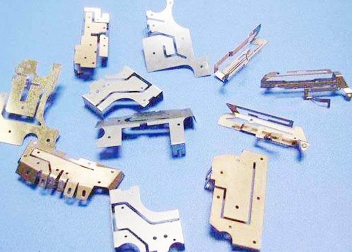
Figure 2 shows different mobile phone antennas. Their principle is the design of the planar inverted F antenna PIFA antenna.
This inverted L-shaped problem is almost the same as the previous ones and will not be explained again. The inverted L antenna is not as effective as the inverted F antenna because the inverted F antenna has a ground feed point, which can effectively adjust the frequency.
There are many PCB board antennas on the market, some of which are made by the manufacturers themselves through simulation.
The second type of patch ceramic chip antenna
This ceramic chip antenna is made into a patch element, as shown in Figure 3.
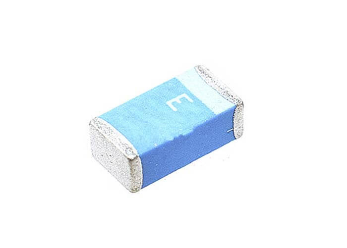
One end of this antenna is connected to RF and one end is grounded. The principle of a ceramic antenna is to turn the high-frequency electric field formed between the antenna and the ground into electromagnetic waves through an electrode called an antenna, which can be emitted and transmitted to a distant place.
Place the ceramic patch antenna on the side of the board, ground it while connecting to the RF signal, and hollow out all layers of copper foil below, so that at least two of the four directions are empty, which has a good effect on the antenna. Don’t forget to ground it. The copper foil must be punched with grounding vias and punch a little more.
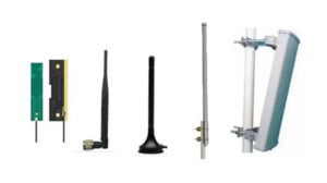
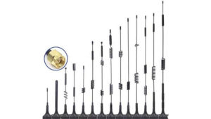
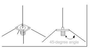
This kind of antenna is shown in Figure 4. This kind of antenna has the best effect. It is placed in space and has the best radiation effect, but the cost is also a bit more expensive and it takes up a lot of space, which can only be exposed outside the case.
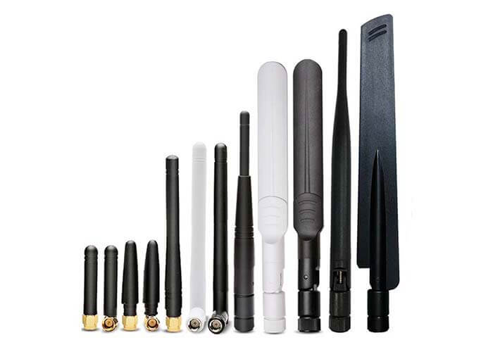
This kind of rubber duck antenna should pay attention to the problems in PCB design
The antenna body of the inverted-F PIFA antenna can be linear or sheet-shaped, and the size of the Bluetooth antenna can be reduced when an insulating material with a higher dielectric constant is used. As a kind of onboard antenna, the inverted F antenna has a low design cost but adds a certain volume, and is the most common one in practical applications. The antenna is generally placed on the top layer of the PCB, and the ground is generally placed on the top layer and near the antenna, but the ground must not be placed around the antenna, and the surrounding area should be a clear space.
The length of a meander antenna is more difficult to determine. The length is generally slightly longer than a quarter-wavelength, and its length is determined by its geometric topological space and area. The meander antenna is generally a PCB package, that is, an onboard antenna. Like the inverted F type, the antenna is generally placed on the top layer of the PCB, and the ground is generally placed on the top layer and near the antenna, but the ground must not be placed around the antenna, and the surrounding area should be a clear space.
Note:
The antenna length calculation formula:
The length of the antenna (m)=(300/f)*0.25*0.96
Where f is the frequency (MHz), 0.96 is the wavelength shortening rate
The length of the Bluetooth antenna is about 300/2.4G*0.25*0.96, which is about 31mm
The ceramic antenna is another miniaturized antenna suitable for Bluetooth devices. The types of ceramic antennas are divided into bulk ceramic antennas and multilayer ceramic antennas. Since the dielectric constant of the ceramic itself is higher than that of the PCB circuit board, the use of ceramic antennas can effectively reduce the size of the antenna.
In terms of dielectric loss, the ceramic medium is also smaller than the dielectric loss of the PCB circuit board, so it is very suitable for low power consumption. Used in the Bluetooth module. When designing the PCB, it is sufficient to have a clear space around the antenna and pay special attention to not applying copper.
The 2.4G rod-shaped rubber duck antenna Bluetooth antenna is large, but the transmission distance is stronger than other antennas. When designing the PCB antenna in the rubber housing, the surrounding area of the antenna should be the same as the above-mentioned three antenna designs.
1) The antenna’s signal (frequency greater than 400MHz) is easily attenuated, so the distance between the antenna and the nearby ground must be at least three times the line width.
2) For microstrip lines and strip lines, the characteristic impedance is related to the thickness, line width, vias, and dielectric constant of the board.
3) Vias will produce parasitic inductance, and high-frequency signals will cause very large attenuation, so try not to have vias when routing the RF line.
When you use a smartphone to make calls, send text messages, play online games, sufer to internet, etc. A series of communication behaviors every day, have you ever thought that all of this is achieved through the antenna module on the phone? of. If there is no antenna, the smartphone will become a stand-alone game console.
Now you talk to people about the antenna of your mobile phone, and some people will even ask you: “An antenna? My mobile phone does not have an antenna. In what era, there is still an antenna.”
The embedded antenna placed internal of the mobile phone is called the built-in antenna.
Simply put, there are basically two types of built-in antennas: PIFA antennas and MONOPOLE antennas.
If the PIFA antenna designs the environmental structure according to the requirements, the electrical performance is quite superior, including the SAR (Specific Absorption Rate, which mainly measures the amount of radiation absorbed by the human body), which is the preferred solution for the built-in antenna.
It is suitable for mobile phone products with a certain thickness, folding, sliding cover, screwing cover, and bar machines.
If the MONOPOLE antenna is designed according to the requirements of the environmental structure, the electrical performance can reach a higher level. The disadvantage is that the SAR is slightly higher. It is not suitable for folding and sliding cover machines and has advantages in bar machines and ultra-thin bar machines.
Let’s take a look at the built-in antennas of several mobile phones.
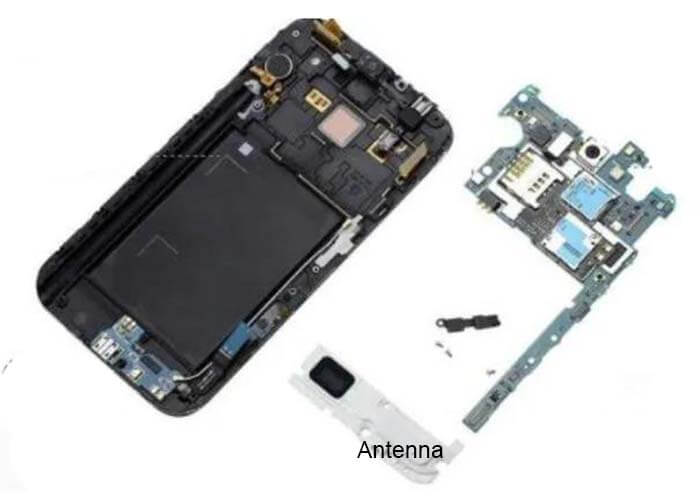
Antenna in Samsung Galaxy Note 2
The white part at the bottom is the antenna module.
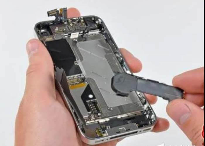
Antenna in iPhone 4S
iPhone 4S also puts the antenna on the bottom of the phone, but unlike Note2, it also has an external metal antenna.
Antenna in iPhone 6
The antenna of the iPhone 6 was moved to the top of the phone. Similarly, the metal backshell was brutally divided.
The earliest big brother mobile phone was an external antenna, which was a low-frequency analog signal antenna. This design is still being adopted by walkie-talkies until now.
In the 2G era, built-in antennas were used from NOKIA, which was stamped from thin stainless steel sheets. Later, in order to reduce costs, they were replaced by FPC (printed circuit boards). FPC is characterized by its soft material and can be attached to curved surfaces. The turning point, it has advantages over metal antennas in terms of space utilization. FPC antennas are still the mainstream antenna technology until now.
Later, with the development of technology, the LDS antenna technology was developed, which is to directly engrave the antenna with a laser on a specially processed plastic molding material. This technology is commonly used in current mid-to-high-end mobile phones and is usually used on the main antenna. The speaker box is made together to save space.
Due to the complex communication capabilities of current mobile phones, antennas with different functions need to be designed, and different technologies will be used in combination.
Multi-input Multi-output (MIMO) is an abstract mathematical model used to describe a multi-antenna wireless communication system. It can use multiple antennas at the transmitting end to send signals independently while using multiple antennas at the receiving end Receiving and restoring the original information is a concept of space-division multiplexing.
MIMO can greatly increase the data throughput and transmission distance of the system without increasing bandwidth or total transmission power consumption. The core concept of MIMO is to use the spatial freedom provided by multiple transmitting antennas and multiple receiving antennas to effectively improve the spectrum efficiency of the wireless communication system, thereby increasing the transmission rate and improving the communication quality.
MIMO technology can be used in wireless communication networks to communicate with base stations, and it can also be used in WiFi networks to communicate with wireless routers. We usually use AxB MIMO to indicate the number of antennas. For example, 2×2 MIMO means 2 channels of transmission and 2 channels of reception, and the theoretical transmission capacity is twice that of SISO.
In the future 5G network, it is foreseeable that terminals will generally adopt a larger number of MIMO technologies.
5G antennas, the size remains the same, the 5g antenna needed quantity increases
The antenna is an important part of wireless communication equipment, used to transmit and receive electromagnetic wave signals. The antenna is a wire with a specified length, which can be manufactured on PCB (Printed Circuit Board) and FPC (Flexible Circuit Board).
The length of the antenna has a strong correlation with the wavelength of the wireless signal. Generally, it is required to be 1/4 or 1/2 of the electromagnetic wavelength. For example, in the 900Mhz frequency band in the 2G era, the electromagnetic wavelength is 20-30cm, and the antenna size is about 7.5cm.
The current 4G communication band is 0.7-2.7GHz, and the main communication frequency band used by 5G is also below 6GHz. Therefore, there will be no major changes in the size of mobile phone antennas using the 5G Sub-6G frequency band, and it will still be at the centimeter level.
However, in order to achieve higher speed requirements, 5G will use more antennas, that is, MIMO technology. For example, 4×4 MIMO has 4 transmitter antennas and 4 collector antennas.
The increase in the number of antennas will require the shape of multiple antennas to be re-arranged, putting new requirements on the back cover and wiring of the mobile phone to achieve better efficiency. Huawei mate30 pro 5G integrates a total of 21 antennas, including 14 5G antennas.
In the future, antenna technology is getting better and better, and the difficulty of antenna design will become higher and higher.
What are the common types of antennas? How to choose the right types of antennas for the devices? The types of antennas classification The antenna is
For a wireless system, a problem needs to be considered in the 433MHz antenna design. The 433MHz antenna design is a very precise task. A
The 1/4 wave antenna is the simplest form of a vertical antenna. It provides good performance combined with an omnidirectional radiation pattern and simplicity of

After the read of the article of Secrets of RF Circuit Design, you will learn about the Secrets of RF Circuit Design. Successful RF design must

The objective of this article is to give 5 RF circuit design tutorials to circuit designers who would like to get acquainted with RF circuit
After reading this How to Make A RFID Antenna Design article, you will learn about: What is an RFID antenna? What are the classifications of
| Cookie | Duration | Description |
|---|---|---|
| cookielawinfo-checbox-analytics | 11 months | This cookie is set by GDPR Cookie Consent plugin. The cookie is used to store the user consent for the cookies in the category "Analytics". |
| cookielawinfo-checbox-functional | 11 months | The cookie is set by GDPR cookie consent to record the user consent for the cookies in the category "Functional". |
| cookielawinfo-checbox-others | 11 months | This cookie is set by GDPR Cookie Consent plugin. The cookie is used to store the user consent for the cookies in the category "Other. |
| cookielawinfo-checkbox-necessary | 11 months | This cookie is set by GDPR Cookie Consent plugin. The cookies is used to store the user consent for the cookies in the category "Necessary". |
| cookielawinfo-checkbox-necessary | 11 months | This cookie is set by GDPR Cookie Consent plugin. The cookies is used to store the user consent for the cookies in the category "Necessary". |
| cookielawinfo-checkbox-performance | 11 months | This cookie is set by GDPR Cookie Consent plugin. The cookie is used to store the user consent for the cookies in the category "Performance". |
| viewed_cookie_policy | 11 months | The cookie is set by the GDPR Cookie Consent plugin and is used to store whether or not user has consented to the use of cookies. It does not store any personal data. |
WhatsApp us