After reading this How to Make A RFID Antenna Design article, you will learn about:
What is an RFID antenna?
What are the classifications of RFID antennas?
What are the RFID antenna types?
How to design an RFID antenna?
How to make RFID antennas?
etc.
What is an RFID antenna?
RFID Antenna is a type of antenna used for the RFID application.
RFID is a non-contact radio frequency identification technology between tags and readers and is generally used in smartphones, smart homes, and Internet of Things IoT terminal devices. As of 2020, with the rapid development of the Internet of Things, more and more electronic terminal equipment products will basically use RFID technology, including NFC-enabled terminal equipment.
The Internet of Things is regarded as the third wave of the information industry after computers and the Internet. In the process of its realization, it requires the cooperation of many high-tech technologies such as communications, sensors, RFID, and positioning.
The combination of RFID, Internet, communication, and other technologies can realize the tracking and information sharing of global items. Therefore, it is considered an important cornerstone for the realization of the Internet of Things and is listed as one of the top ten important technologies in the 21st century.
In the process of wireless communication, the antenna is an indispensable component. RFID uses radio waves to transmit information, and the generation and reception of radio waves need to be completed through an antenna. When the electronic tag enters the working area of the reader/writer antenna, the electronic tag antenna generates enough induced current to obtain energy to be activated.
For the RFID system, the antenna is a vital part, and it is closely related to the performance of the system.
The RFID system has been widely used in many fields, such as logistics management, manufacturing, book management, identity recognition, road automatic toll collection, and other fields.
What is the RFID radio frequency identification technology?
The radio frequency identification system consists of three parts:
- Scanning antenna
- Transceiver with a decoder to interpret data
- Transponder with information, RFID tag.
The scanning antenna emits radio frequency signals in a relatively short range. There are two things about radiofrequency radiation.
- It provides a way to communicate with the transponder (RFID tag)
- It provides communication energy for RFID tags
This is an absolutely critical part of technology. RFID tags do not need to contain batteries, so they can remain usable for a long period of time (possibly decades).
The scanning antenna can be permanently fixed on the surface. A handheld antenna is also provided. They can take any shape you need; for example, you can build them in a door frame to receive data from passing people or objects.
When the RFID tag passes through the area of the scanning antenna, it will detect the activation signal from the antenna. This will wake up the RFID chip, and then transmit information on its microchip for the scanning antenna to pick up.
In addition, the RFID tag can be one of two types. Active RFID tags have their own power source; the advantage of these tags is that the reader can go farther and still receive signals.
Even though some of these devices have a service life of up to 10 years, they have a limited service life. However, passive RFID tags do not require batteries, can be smaller, and have an almost unlimited service life.
In many cases where barcodes or other optical reading technologies are useless, RFID tags can be read.
- The label does not have to be on the surface of the object (so it will not be worn)
- Reading time is usually less than 100 milliseconds
- It is possible to read a large number of tags at one time instead of reading item by item.
- Essentially, this is how RFID works.
What are the principles of RFID technology?
The RFID application system is mainly composed of two parts: a reader and an RFID card. Among them, the reader is generally used as a computer terminal to read, write and store data on the RFID card. It is composed of a control unit and a high-frequency communication module and an antenna composition.
The RFID card is a passive transponder, which is mainly composed of an integrated circuit (IC) chip and its external antenna. The RFID chip is usually integrated with radio frequency front-end, logic control, memory, and other circuits, and some even integrate the antenna together on the same chip.
The basic working principle of the RFID application system is that after the RFID card enters the radio frequency field of the reader, the induced current obtained by its antenna is used as the power supply of the chip through the booster circuit, and the induced current with information is detected by the radio frequency front-end circuit to detect the digital signal.
It is sent to the logic control circuit for information processing; the information that needs to be replied to is obtained from the memory and sent back to the RF front-end circuit through the logic control circuit, and finally sent back to the reader through the antenna.
The antenna plays a key role in the realization of data communication between the RFID card and the reader.
On the one hand, the passive RFID card chip needs to get enough energy in the electromagnetic field generated by the reader antenna through the antenna to start the circuit work; on the other hand, the antenna determines the communication channel and communication between the RFID card and the reader the way.
The RFID tag antenna is the transponder antenna of the RFID tag and is a communication induction antenna. An RFID electronic tag transponder is generally composed of a chip. RFID tag antennas are divided into metal etching antennas, printed antennas, copper-plated antennas, etc. due to different materials and manufacturing processes.
What are the classifications of RFID antennas?
There are many forms of RFID antennas. According to their use, they can be divided into transmitting antennas and receiving antennas; according to their use bands, they can be divided into long, medium, short, ultra-short wave antennas, microwave antennas, and microstrip antennas. In addition, we can classify them according to their working principle and structure.
In order to facilitate the analysis and study of the performance of antennas, antennas are generally divided into two categories according to their structure. One is a linear antenna composed of metal wires with a radius much smaller than the wavelength, and the other is a metal or medium with a size larger than the wavelength.
A planar antenna is composed of a surface. Linear antennas are mainly used for long, medium, and short wave frequency bands, and planar antennas are mainly used for centimeter or millimeter-wave frequency bands;
For very high-frequency bands, linear antennas are generally used, while ultra-high frequency bands are used for both linear and planar antennas. The basic working principle of the linear antenna and the planar antenna is the same.
What are the RFID antenna types?
The RFID antenna is a device that receives or radiates the front-end radio frequency signal power in the form of electromagnetic waves. It is an interface device between the circuit and space and is used to realize the energy conversion between the guided wave and the free space wave.
In the RFID radio frequency identification system, antennas are divided into two categories: electronic RFID electronic tag antennas and reader-writer antennas, which are responsible for receiving energy and transmitting energy respectively.
Current RFID radio frequency identification systems are mainly concentrated in LF, HF (13.56MHz), UHF (860-960MHz), and microwave frequency bands. The principles and designs of RFID radio frequency identification system antennas in different working frequency bands are fundamentally different.
The gain and impedance characteristics of the RFID radio frequency identification antenna will affect the range of the RFID automatic identification system. The working frequency band of the RFID radio frequency identification system in turn has certain requirements on the antenna size and radiation loss. Therefore, the design of the RFID radio frequency identification antenna is related to the success of the entire RFID automatic identification system.
Near-field antenna type
For the LF and HF frequency bands, the system works in the near field of the antenna, and the energy required by the RFID electronic tag is obtained by radiating the near field from the coupling coil of the reader through inductive coupling. The working mode is inductive coupling.
The electric field strength decays with the third power of the distance, the magnetic field strength decays with the second power of the distance, the phase difference of the electromagnetic field component is 90 ○, the Poynting vector is an imaginary number, and the energy does not radiate outward, and only electric and magnetic energy is carried out near the surface of the antenna exchange.
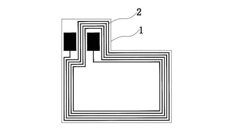
Because the electromagnetic wave propagation problem is not actually involved in the near field, the antenna design is relatively simple, and generally, a coil-type antenna with a simple process and low cost are used.
The coil antenna is essentially a resonant circuit. At the specified operating frequency, when the inductive impedance is equal to the capacitive impedance, the coil antenna will resonate.
The resonant frequency of the resonant circuit is (L is the coil inductance of the antenna, and C is the coil capacitance of the antenna). The resonant working frequency of the coil antenna of the HF segment RFID radio frequency identification is usually 13.56MHz. The RFID radio frequency identification application system is through this frequency carrier Realize two-way data communication.
Certain application environments require RFID coil antennas to be small in appearance and require a certain working distance, which will inevitably reduce the mutual inductance of the coil antennas.
In order to solve this problem, we usually insert a ferrite material with high permeability μ inside the coil to increase the mutual inductance, thereby compensating for the reduced cross-section of the coil. Obviously, the working principle of the near-field antenna is completely similar to ours The well-known transformer principle, theory is relatively simple.
Far-field antenna type
Below, we focus on the theoretical analysis and structure of the far-field antenna. For UHF and microwave frequency bands, the reader antenna must provide energy for the RFID electronic tag or wake up the active RFID electronic tag, and the working distance is relatively long, generally located in the far-field of the reader antenna.
The electric field strength and the magnetic field strength decay with the first power of the distance, and the direction of the electric field and the magnetic field are perpendicular to each other, and both are perpendicular to the direction of propagation.
The Poynting vector is a real number, and the electromagnetic field radiates energy outward in the form of electromagnetic waves. At this time, antenna design has a greater impact on system performance, and dipole or microstrip patch antennas are mostly used.
A dipole antenna, also called asymmetrical dipole antenna, consists of two straight wires of the same thickness and length arranged in a straight line.
The signal is fed in from the two endpoints in the middle, and a certain current distribution will be generated on the two arms of the dipole, and this current distribution will excite an electromagnetic field in the space around the antenna. Generally used in RFID radio frequency identification electronic RFID electronic tags Is a zigzag type folded dipole antenna.
Microstrip patch antenna type
Microstrip patch antennas are usually made of a thin layer of metal patch attached to the ground plane.
The microstrip patch antenna is light in weight, small in size, and thin in section. The feeder and matching network can be manufactured at the same time as the antenna and integrated with the printed circuit of the communication system. The patch can be manufactured by photolithography, which is low in cost and easy to mass-produce.
Microstrip patch antennas have become the protagonist of printed antennas due to the diversification of their feed modes and polarization systems, as well as the integration of feed networks and active circuits.
Generally, the distance between the radiating conductor of the microstrip patch antenna and the metal floor is a few tenths of a wavelength. It is assumed that the radiating electric field does not change along with the horizontal and vertical directions of the conductor, but only changes along the length of the conductor, which is about half a wavelength.
The radiation of the microstrip patch antenna is basically caused by the fringe field at the open edge of the patch conductor, and the direction is basically determined. Therefore, the microstrip patch antenna is very suitable for RFID radio frequency identification application systems where the communication direction does not change much.
How to design an RFID antenna?
RFID antenna design points
RFID antenna structure and environmental factors have a great influence on RFID antenna design performance. The structure of the RFID antenna determines the characteristics of the antenna pattern, impedance characteristics, standing wave ratio, antenna gain, polarization direction, and operating frequency band.
The RFID antenna characteristics are also affected by the shape and physical characteristics of the attached object. For example, if the magnetic field cannot penetrate metal and other magnetic materials, the shape of the magnetic line of force near the metal object will change, and the magnetic field energy will cause eddy currents on the metal surface.
Eddy current will produce a magnetic flux that resists excitation, which will cause the magnetic flux on the metal surface to be greatly attenuated. The energy emitted by the UHF reader antenna is absorbed by the metal, and the reading and writing distance will be greatly reduced.
In addition, the liquid has the effect of absorbing electromagnetic signals, the elastic base layer will cause the deformation of RFID electronic tags and antennas, and broadband signal sources (such as engines, water pumps, generators) will produce electromagnetic interference, etc., which must be carefully considered when designing antenna place.
At present, the research field has proposed a variety of RFID antenna design solutions based on the above characteristics of antennas, such as the use of zigzag antennas to solve the size limitation, and the use of inverted F antennas to solve the reflection problem of metal surfaces.
The goal of the antenna is to transmit the maximum energy into and out of the circuit, which requires careful design of the matching between the antenna and the free space and its circuit. The higher the matching degree of the antenna, the better the radiation performance of the antenna. When the operating frequency increases to the ultra-high frequency area, the matching problem between the antenna and the RFID electronic tag chip becomes more severe.
In traditional RFID antenna design, we can control the size and structure of the antenna and use an impedance-matching converter to match the input impedance to the feeder. Generally, RF antenna development is based on 50 or 75-ohm impedance, but in an RFID antenna design radio frequency identification system, the input impedance of the chip may be any value, and it is difficult to accurately test under working conditions, and the antenna design is difficult to achieve the best.
For short-distance RFID radio frequency identification applications, the RFID antenna is generally integrated with the reader. For long-distance RFID radio frequency identification systems, the reader antenna and reader are generally separated Structure, connected by impedance-matched coaxial cable.
Generally speaking, directional antennas are more suitable for RFID electronic tag applications because they have less return loss; because the RFID electronic tag placement direction is uncontrollable, the reader antenna generally adopts circular polarization.
RFID reader antennas require a low profile, miniaturization, and multi-band coverage. For separate readers, the design of the antenna array will also be involved.
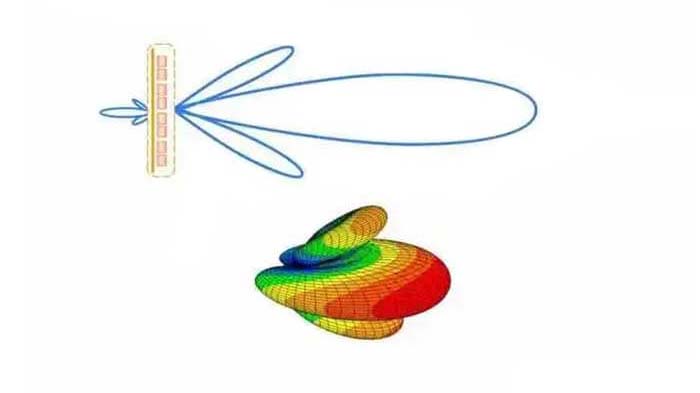
Foreign countries have begun to study the application of smart beam-scanning antenna arrays to readers. The reader can intelligently turn on and off different antennas according to a certain processing sequence so that the system can perceive the RFID electronic tags covered by different antennas and increase the system coverage.
RFID antenna design process
Different frequency bands and different application fields have different requirements for the structure of the electronic tag antenna.
In general, RFID antenna design tends to follow the following goals.
(1) Miniaturize the RFID antenna volume as much as possible;
(2) The RFID antenna provides the largest possible signal to the chip;
(3) The directivity of RFID antenna coverage should be as large as possible;
(4) The polarization of the RFID antenna matches the interrogation signal of the reader;
Example of NFC RFID antenna design by PDS process
PDS is a process for printing cell phone antennas (pad printing), which mainly involves applying a conductive silver paste to the surface of the workpiece and then printing the silver paste in multiple layers to form a conductive three-dimensional circuit.
PDS (PRINTING Direct Structure) technology is a built-in antenna manufacturing method that enhances radio frequency (RF) characteristics by printing conductive ink directly on the inside of the phone. It is a patented technology that enhances RF characteristics and reliability by forming an environmentally friendly electroless plating layer with conductive ink on the printed part of a specific plastic material.
The antenna pattern is printed on the upper surface of the plastic case through the PDS process, and the antenna pattern needs to be extended from the side of the plastic case to the lower surface to connect with the feed point part of the cell phone circuit board so that the antenna and the circuit board can be connected successfully.
The advantage of PDS is that the circuit can be printed directly without special laser-modified material, which can significantly reduce the cost, and it is more difficult to deal with the antenna design in the corner, the through-hole structure can realize the circuit conduction.
With the determination of mobile payment standards, many high-end smart products begin to be equipped with mobile payment functions as standard. Products with mobile NFC payment functions need an NFC chip and NFC antenna.
NFC antenna is based on RFID RFID technology, using transformer co-coupling matching to do the hardware processing scheme of communication, and through the processor’s communication instructions to complete the data transmission process of verification, software and hardware environment through RFID modulation processing, and through the matching circuit adjustment and design and production success.
NFC antenna is a kind of near-field coupling antenna, using the form of magnetic coupling, that is, using the way of coil coupling.
NFC system can provide users with card mode, read-write mode, and point-to-point three services, communication distance is relatively short, high security, and simple and convenient operation.
How to manufacture RFID antennas?
Three main processes of RFID antenna manufacturing
In order to adapt to the different requirements of RFID performance parameters in different application scenarios, various RFID antenna manufacturing processes have emerged. At present, the most commonly used RFID antenna manufacturing processes mainly include coil winding method, etching method, and printing method.
Coil winding method
When using the coil winding method to make an RFID tag antenna, the tag coil must be wound and fixed on a winding tool. The antenna coil is required to have a large number of turns. The coil can be either a circular ring or a rectangular ring.
This method is generally used for RFID tags with a frequency range of 125 to 134KHz. The shortcomings of using this processing method to make antennas are obvious, which can be mainly summarized as high cost, low production efficiency, and insufficient consistency of processed products.
Etching method
The etching method usually uses copper or aluminum to make antennas. This method is similar in the production process to the etching process of flexible printed circuit boards. The etching method can be applied to mass manufacture 13.56MHz, UHF bandwidth electronic tags, it has the advantages of a fine circuit, low resistivity, good weather resistance, stable signal, and so on. However, the shortcomings of this method are also obvious, such as cumbersome production procedures and low productivity.
Printing method
The printed antenna is a circuit in which conductive ink is directly printed on an insulating substrate (or film) to form an antenna circuit. The main printing method has expanded from only using screen printing to offset printing, flexographic printing, gravure printing, and other production methods.
The printing method is suitable for the mass production of 13.56MHz and RFID UHF electronic tags. It is characterized by fast production speed, but due to the large resistance of the circuit formed by conductive ink, its application range is limited to a certain extent. Due to the advancement of printed antenna technology, the cost of RFID tags has been effectively reduced, which has promoted the popularization of RFID applications.
You may also be interested in the below articles.
6 Rules And Techniques For PCB Wiring