What is a 915 MHz Yagi Antenna LoRaWan Directional Antenna?
The 915 MHz Yagi Antenna LoRaWan Directional Antenna style CTRF-ANTENNA-YAGI-0915-7619-SMA antenna item is a 9 Element Yagi Antenna 13dBi High-gain Lora Antenna 915MHz Directional Antenna manufactured by C&T RF Antennas Inc for Lora, Lorawan applications.
The 9 Element 13dBi High-gain 915 MHz Yagi Antenna LoRaWan Directional Antenna Lora Antenna is supplied by C&T RF Antennas Inc, the professional Yagi-Uda antenna and directional Yagi antenna manufacturer in China.
We provide the RF wireless antenna with many antenna types such as Through-hole Mount Antennas, Magnetic Mount Antennas, Rubber Duck Antennas, Fiberglass Antennas, PCB Antennas, FPC Antennas, Spring Coil Antennas, Sector Antennas, Yagi antennas, etc.
C&T RF Antennas Inc provides the indoor-outdoor antenna with many antenna frequencies such as Cellular, 6G, 5G, 4G, 3G, NB-IoT, GNSS, GPS, Dual-band Wifi, 5.8 GHz, 2.4 GHz, 169MHz, 230MHz, 315MHz, 433MHz, 868MHz, 915MHz LoRa, UWB, RFID, ADS-B, etc.
Contact us for more 915 MHz Yagi Antenna LoRaWan Directional Antenna Lora Antenna details such as the 915 MHz Yagi Antenna LoRa Directional Antenna datasheet, 915 MHz Yagi Antenna LoRa Directional Antenna pricing, 915 MHz Yagi Antenna LoRa Directional Antenna inventory, or other Yagi antenna styles.
915 MHz Yagi Antenna LoRaWan Directional Antenna Specifications
915 MHz Yagi Antenna LoRaWan Directional Antenna Electrical Specifications | |
| RF Antenna Type | Yagi Antenna |
| Model | CTRF-ANTENNA-YAGI-0915-7619-SMA |
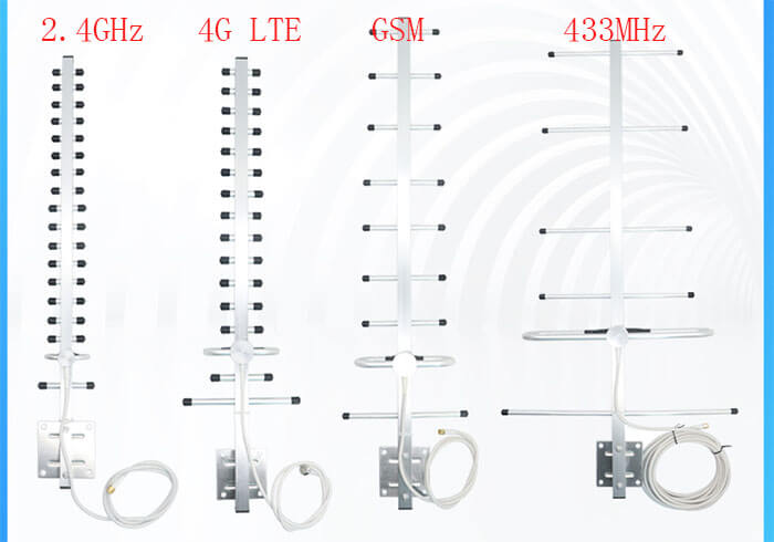
| Frequency | 915 MHz |
| Gain | 13dBi |
| VSWR | ≤1.8 |
| Impedance | 50 Ω |
| Polarization | Vertical |
| Cable Type | RG58 |
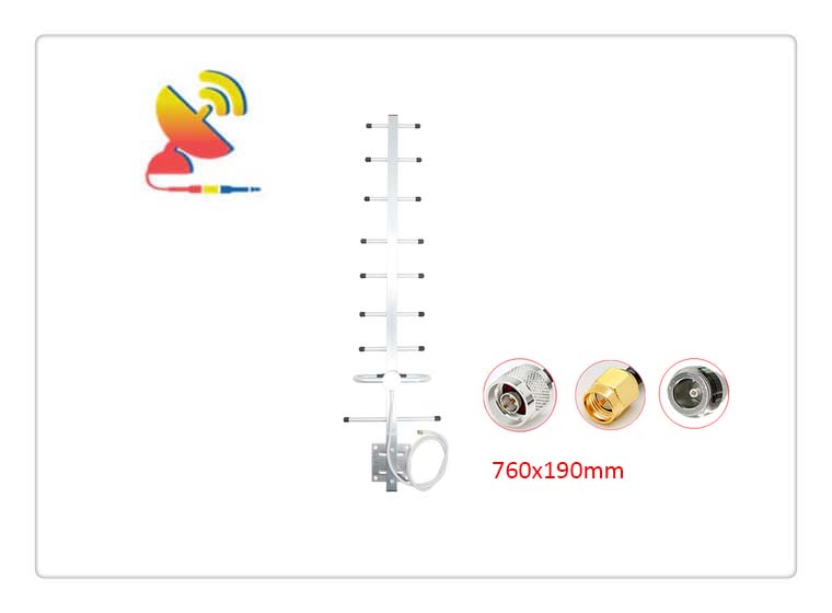
| Connector | SMA-J, (SMA-K, N-Type Male, N-Type Female connectors are choosable) |
| Cable Length | 1Meter |
| Max Power | 50W |
| Lightning Protection | DC-Ground |
915 MHz Yagi Antenna LoRaWan Directional Antenna Mechanical Specifications | |
| Dimension | 760x190mm |
| Weight | Approx. 600g |
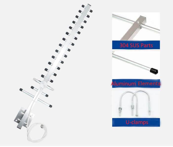
| Material | Aluminum/SUS304 |
| Operation Temperature | -40˚C~+85˚C |
| Storage Temperature | -40˚C~+80˚C |
| Element | 9 |
| Mounting | U Clamp/Adsorption |
| Safety Emission and other | RoHS Compliant |
| Applications | LoRa/GSM/ISM/IoT/M2M, etc. |
What is the principle of the Yagi antenna?
With the antenna electrical indicators are closely related to the wavelength λ length slightly longer than N/4 integer times the wire is inductive, length slightly shorter than λ/4 integer times the wire is capacitive.
As the main oscillator, L uses about λ/2 long half-wave symmetric oscillator or half-wave folded oscillator, in the center frequency point of work in the resonant state, the impedance presented as a pure resistance, and reflector A than the main oscillator is slightly longer, showing inductance.
Assuming that the two spacing a for λ/4, to receive the state as an example, from the antenna in front of a point over the electromagnetic wave will first reach the main oscillator, and produce induced electric potential ε1 and induced current I1, and then After the distance of 1/4, the electromagnetic wave will arrive at the reflector and generate the induced electric potential ε2 and induced current I2.
Because of the spatial difference A/4 distance, so ε2 than ε1 lag 90, and because the reflector is inductive I2 than e2 lag 90 °, so I2 than ε1 lag 180, reflector induction current I2 radiation to the main oscillator to form the magnetic field H2 than I2 lag 90 °, according to the law of electromagnetic induction H2 in the main oscillator generated by the induction potential ε1 than H2 lag 90 °.
That is, ε1 ‘ than ε1 lagged 360 °, that is, the reflector in the main oscillator generated by the induction potential ε1 and electromagnetic signal source directly generated by the induction potential ε1 is in the same phase, and the antenna output voltage is the sum of the two.
The same reasoning can be deduced that the signal to a point behind the antenna, the reflector in the main oscillator generated induction electromotive force, and the signal directly generated induction electromotive force is in phase, to play a role in offsetting the output.
And lead B, C, D, etc. are slightly shorter than the main oscillator, and impedance is capacitive, assuming that the oscillator spacing b, c, d is also equal to λ/4, according to the above method can also be introduced to lead the signal over the front to play a role in enhancing the output of the antenna.
The reflector can effectively eliminate the antenna directional map after the flap, and the diverter together enhance the sensitivity of the antenna to the front signal, so that the antenna has a strong directional, improving the antenna gain. For the transmitting state, the derivation process is also the same.
In the actual production process, through meticulous design and proper adjustment of the length of each oscillator and its spacing, we can get the Yagi antenna working at different center frequency points, with certain bandwidth, certain impedance value, and a better end-fire directional map.
915 MHz Yagi Antenna LoRaWan Directional Antenna Features

Reviews
There are no reviews yet.