Today, we talk about the NFC technology architecture and the NFC technology standards involved.
NFC technology evolved from contact-free radio frequency identification (RFID), which has a transmission range of several meters or even tens of meters and can only achieve information reading and determination, while NFC technology emphasizes information interaction.
Near-field communication is operating at 13.56 MHz frequency within a distance of 20 cm, and its transmission speed is 106 Kbit/sec, 212 Kbit/sec, or 424 Kbit/sec.
The Near Field Communication Forum has defined three modes of operation (PDF).
Peer-to-peer mode (P2P mode)
Support two near-field communication devices to communicate with each other to exchange information and share files.
Reader/writer mode
Enable near-field communication devices to read relevant information from posters or electronic tags for exhibition information.
Card emulation mode
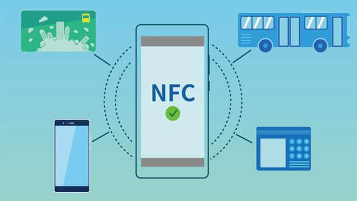
Near-field communication devices can act like smart cards, allowing users to pay for retail purchases and transportation.
NFC technology cell phone built-in NFC chip, forming part of the RFID module, can be used as RFID passive tags, used to pay fees; can also be used as an RFID reader for data exchange and collection.
From the application, the model is divided into NFC card simulation, reader, and peer-to-peer three modes.
Card simulation mode is usually also known as the read mode, cell phone terminals can be simulated as an ordinary contactless card is read by POS, this mode is usually inherited from the now widely used applications.
For example, bank cards, access control cards, bus cards, etc., NFC technology cell phones as a carrier and play the advantages of cell phones in the network, multimedia, human-computer interaction, application scenarios are similar to the existing mode;
The reader mode is often referred to as the main reader mode, where the cell phone terminal can read the contents of a contactless card or a contactless tag, and this mode may inherit both existing applications.
For example, the NFC technology cell phone can be used as a POS machine to read existing bank cards and bus cards, and it can also be the latest application scenario defined by NFC technology, such as using the NFC technology cell phone to read the standard data in the NFC technology-defined tag to achieve the functions of electronic business cards, electronic posters, WIFI connection, etc;
Point-to-point mode refers to two cell phone terminals in close proximity to directly transfer data through touch, which is a new mode defined by NFC technology, compared with Bluetooth, WIFI has two characteristics of close proximity and simple configuration, theoretically, you can achieve any data interaction between two cell phones through a simple touch.
For example, synchronization of schedules, location sharing, business card exchange, and other functions.
NFC technology principle
NFC technology architecture, and NFC technology standards involved.
The NFC function of the cell phone terminal is composed of NFC Controller, NFC protocol stack, SE, SE access API, SE access control, and AP access SE chip, whose main functions are as follows.
- NFC Controller: i.e. NFC chip, which realizes the processing of analog and digital protocols defined by NFC card analog, reader, and peer-to-peer modes;
- NFC protocol stack: configure the NFC chip working mode and implement the standards defined by NFC Forum. 3;
- SE: that is, the security chip, all services involving sensitive data, and encryption operations (such as bank cards, and bus cards) need to be handled by a separate security chip;
- SE access API: open the interface to the client to access the SE to achieve balance reading, air top-up, and other functions;
- SE access control: control and authorize SE access to ensure SE security;
The chip will be different when the SIM card is SE, for example, this chip is a Modem. The above different modules can be combined to achieve different NFC functions, which can be roughly divided into two types: simple NFC and NFC with SE.
Simple NFC refers to the NFC terminal with only NFC Controller and NFC protocol stack. Since it does not have SE, this terminal can only support the NFC reader and point-to-point functions mentioned in the previous blog post and realize NFC functions such as business card exchange, tag reading, and other NFC functions not related to security.
Because of the simple composition and the native system of Android 2.3 or above that has achieved these functions, most of the NFC terminals on the market are this kind of simple NFC.
Compared with simple NFC technology, NFC terminals with SE are integrated with a separate security chip SE, which can support security applications introduced by card simulation mode (such as bank cards, bus cards, etc.) in addition to the reader and point-to-point mode, and can support both contactless cards swiping on POS machines and client access to SE to realize functions such as balance reading of bank card and bus card stored in SE and over-the-air top-up.
There is no doubt that the NFC terminal with SE function is more concern by users, operators, and banks at present, and the SE approach taken by different organizations in promoting the NFC terminal is also different.
At present, there are three main types of SE, namely SIM card, terminal built-in SE chip, and microSD card, which represent the natural response of operators, terminal manufacturers, and banks from their own position in the industry chain and in the initial stage of promoting NFC terminals.
From the current development situation, the operator-driven NFC terminal solution with SIM card as SE (commonly known as SWP solution) is the fastest and best developed, led by the operator industry organization GSMA Association, more than 50 operators in the world (including China Mobile, China Unicom and mainstream operators in Europe, the United States, Japan, and Korea) have announced their support for the solution, and nearly 40 million terminals have been sold worldwide. Continued growth is expected in FY13.
NFC-SWP terminal refers to the NFC terminal that supports SWP-SIM cards, that is, the NFC terminal that uses SIM cards as SE. Two parts.
NFC-SWP terminal architecture
(I) NFC non-contact part
It is composed of NFC Controller, NFC technology protocol stack, and SIM card, providing NFC card simulation, reader, and peer-to-peer functions, among which SIM card mainly plays the role of a security module in card mode, and currently does not play a role in the reader and peer-to-peer modes.
The information routing mechanism is different in different modes of the NFC terminal. When the NFC terminal works in card simulation mode, the signal sent by the external POS will be forwarded to the SIM card through NFC Controller for processing, while when the NFC terminal works in reader/writer and peer-to-peer modes, the information read from external cards or cell phones will be forwarded to NFC Controller for resolution and final forwarding. The information read from the external card or mobile phone will be forwarded to the NFC technology protocol stack for parsing and finally forwarded to the operating system or client application for processing.
The technical standards and testing standards of the NFC technology contactless part are relatively complete, mainly completed by ISO, NFC Forum, ETSI, and other standardization organizations, among which.
ISO is mainly responsible for the analog and digital protocols of the underlying NFC air interface, and the RF protocols defined by ISO have been widely used in public transportation, banking, government, and other industries
The main mission of the NFC Forum is to define new NFC technology devices and ensure their interoperability. The NFC Forum defines the data structure and link-layer protocols required for data exchange between new NFC devices on top of the ISO protocols.
ETSI is mainly responsible for developing the interface specification between NFC Controller and SE. Initially, the interface specification developed by ETSI was limited to SIM cards, but now it is widely used as a common interface specification in other forms of SE.
NFC technology standards are relatively complex, and the standards followed in different NFC technology working modes are different, the following are the protocols to be followed in different modes.
Mode RF protocol Intermediate protocols
- Application protocols other protocols application scenarios card simulation mode ISO 14443 no industry regulations
- ETSI 102.613 (SWP) ETSI 102.622 (HCI) compatible with existing equipment reader mode ISO 14443 no industry regulations, no compatibility with existing equipment ISO 14443NFC Forum Tag Type 1-4 NFC Forum NDEF NFC Forum RTD outside custom application protocols
- Interoperable with NFC Forum devices point-to-point mode ISO 18092 NFC Forum LLCP NFC Forum SNEP NFC Forum RTD outside custom application protocols, interoperable with NFC Forum devices Note
a: Intermediate protocols refer to the link layer and data format protocols required for communication between NFC Forum devices note
b: refers to the specific provisions of different industry standards, not in the NFC technology specification system, such as PBOC, EMV, etc. Note
c: NFC RTD specifies several common applications such as URI, contacts, etc. These applications are already known by the Android system and do not need special client support; at the same time, different application parties can also customize application protocols, such as GPS location sharing, but these own application protocols need supporting private client software to identify
An NFC terminal can not only interoperate with a brand new NFC Forum device that conforms to the NFC Forum protocol but also simulate a device identical to an ordinary contactless IC card that is read by the stock contactless POS, so that it can be widely used in the existing contactless environment that users are familiar with, reducing the entry barrier for users, which is very crucial for the initial promotion of a new device.
(2) SIM card access interface
It consists of SE access API, SE access control, and Modem. The biggest difference between cell phones and ordinary contactless IC cards is reflected in the possession of both network functions and human-machine interaction. Therefore, NFC cell phones can engage in rich services that cannot be completed by traditional contactless IC, such as over-the-air top-up and balance inquiry.
All these services require a technical prerequisite, i.e., a standard SIM card access interface that enables the application client to access the SIM card and communicate with the applet in the SIM card. Specifically, three standards need to be supported on the phone.
SIM Alliance Open Mobile API.
Provides a channel for the application client to communicate with the SIM card
Global Platform/GSMA: Secure Element Access Control.
Authorizes the application client to access the corresponding applet in the SIM card
Modem.
It needs to fully support the 3GPP 27.007 standard, support opening SIM card logical channels, and be able to truly implement APDU pass-through in logical communication.
On the one hand, it is necessary for cell phones, especially Modem providers to fully understand the characteristics of NFC service, especially the difference between the logical channel and traditional telecom applications, and improve the product support for APDU transmission on the logical channel, on the other hand, it is also necessary for standardization organizations, operators and manufacturers to work together to improve the test standards and test tools, so as to promote and ensure the maturity of the product.
The radiofrequency sine wave generated by the terminal transmits energy to the tag and then reads data from the tag.
If a tag is within the range of the magnetic field disturbance generated by the sine wave, the tag is energized by the magnetic field disturbance and generates a wave with the opposite frequency of the original sine wave or a change in frequency properties. RFID communication at a very close range is often referred to as a near-pairing system.
The range of a near-pairing system is usually 0 to 1 cm. This means that the tag is next to the reader or pressed against the reader. The advantage of such a close range is that the tag’s battery plant can emit a large amount of energy. This is enough energy to support tag communication without the need for a built-in power supply. Proximity pairing is also beneficial for highly confidential situations.
For example, an NFC-enabled cell phone with an integrated circuit that generates a 13.56 MHz radiofrequency, with an encoder, decoder, antenna, comparator, and hardware that transmits energy to the tag and reads the modulated information in the backscatter. The reader continuously generates the RF signal and observes the received RF signal and reads the information in it.
NFC-enabled devices can exchange data in either active or passive mode. In passive mode, the device that initiates NFC communication also called the NFC technology initiating device (master device), provides the RF field (RF-field) throughout the communication process.
It can choose one of the 106kbps, 212kbps, or 424kbps transmission speeds to send data to another device. The other device called the NFC technology target device (the slave device), does not have to generate an RF field but uses load modulation (load modulation) technology, that is, the data can be transmitted back to the originating device at the same speed.
The NFC technology standard specifies an operating frequency of 13.56 MHz, which is a license-free international common band and is one of the U.S. ISM band 15/18 bands. The data transmission rate is 106 kbps, 212 kbps, or 424 kbps, depending on the communication range, with the maximum transmission rate at 20 cm or about 8 inches, and the actual communication range is only a few inches or no greater than 10 cm. The standard specifies a variety of operating modes.
Inactive mode, either party can initiate a half-duplex transmission using the listen before sending protocol after the transceiver is powered up on both sides of the communication. This feature prevents conflicts when more than one NFC device tries to access a reader, where one device is the initiator and the other is the target.
In passive mode, like an RFID tag, the target is a passive device. The tag gets its operating energy from the magnetic field transmitted by the initiator and then transmits the data to the initiator by modulating the magnetic field (post-scan modulation, a type of AM).
In use because the use of NFC usually encounters spikes in use, it will avoid data link errors caused by different initiators or targets communicating at the same time, so NFC uses a mechanism to listen before talking.
This mechanism allows when the initiating device to send an interrogation signal before detecting the external magnetic field strength to determine whether other devices are communicating, the implementation of this mechanism is called RF Collision Avoidance (RFCA).
Its action behavior is to detect the external magnetic field each time the initiator sends an interrogation signal, and when the magnetic field strength exceeds the threshold strength (Hthreshold=0.1875A/m), it will stop interrogation until the external strength drops below the threshold value.
If it is lower than the threshold value before the interrogation command will start, the detection time is TIDT+nTRFW, n is the chance sampling from 0 to 3: TRFW=512/Fc (RF waiting time), TIDT>4096/Fc (initial delay time).
When the initiating device does not detect a magnetic field exceeding the threshold strength within TIDT+nTRFW, it will first transmit the unmodulated RF field of TIRFG before sending the interrogation signal, where TIRFG must be greater than 5ms.
Since NFC 106kbps is 100% ASK modulation, the entire High/Low signal packet structure is defined in considerable detail. Several of these parameters include the range from 100% down to 5% Am time (t1), 5% Am duration (t2), and Am rise from 5% to 60% time (t4) i.e. overshoot. And 212/424kbps is 8% to 30% of the modulation rate.
NFC technology RF test
NFC technology RF test kit
- Calibration coil.
The coil’s function is to verify the test process, the object to be tested emits the signal is the correct strength and modulation. This coil is a simple antenna architecture, of course, EMCA also detailed all the dimensions, so the coil measured the value of 0.32V (RMS) = 1A / m (magnetic field strength).
- Field Generating Antenna.
Kit for magnetic field emission, the figure also contains a set of antenna matching lines.
- Sense coil.
Sense coil is used to measure the magnetic field strength and modulation of the object to be measured.
- Reference device.
A reference device is used to test the standard parts of the DUT.
NFC technology RF test procedures
- initiating device power test.
This test item is to test whether the magnetic field strength supplied by the initiating device provides sufficient working power to the target.
The signal from the generating antenna to adjust the emission, the calibration coil at the right end of the measured strength of Hmax (7.5A/m), then the reference device with power test line adjustment C2 so that the line resonance point is located at 19MHz (this part of the specification does not elaborate on why the adjustment to 19MHz. 19MHz.
In this inference if 19MHz can reach 3V output when the target is 13.56MHz, the voltage must be super high 3V, the lower limit for this reason), placed in the DUT position, adjust the line R2 so that the voltage value obtained by C3 is 3V.
At this point, the Reference device has been completed, and then the card is used to measure the initiating device, and the card is placed in the override range marked by the initiating device, and the voltage value (C3) measured at any position within this override range cannot exceed 3V.
As for the Hmin test, it is more or less the same as max, with the difference that the resonance frequency of the reference device is tuned to 13.56MHz and the measured voltage value must exceed 3V.
- Load modulation test of the target.
(1)Passive mode
- 106kbps: This test is to verify that the target can modulate the waveform correctly.
- 212/424kbps: High-speed modulation signal measurement is very similar to 106kbps, except that the measurement capture position is changed to FC because subcarrier modulation is not used in these two transmission speeds.
(2) Active mode
The active mode test is not much different from the passive mode, because it is the active mode, so the RF field emission time of the target is measured, the command time, etc.
- load modulation test of the initiating device.
This test is to verify the initiating device modulation mechanism, which can be divided into active mode transmitting and passive mode receiving two.
(1) Active mode transmitting: The calibration coil is placed at any position defined by the initiating device, and the measured waveforms must comply with the specifications set by ECMA 340.
(2) Passive mode receiving: This is to test that the initiating device can correctly receive the signals returned by the passive target. Using the reference device made by the load modulation test line, first, correct the relationship between the corresponding C3 voltage and distance structure, then you can measure the card and the object to be tested by the initiating device, and test the reception of the modulation signal sent by the reference device at the object to be tested. Here we can only discuss some of the test items and please refer to ECMA for detailed tests.
These are the NFC technology knowledge of NFC technology architecture, and NFC technology standards, C&T RF Antennas Inc is the NFC technology antenna manufacturer in China, contact us for the NFC antenna designs.
Besides the NFC technology knowledge article, you may also be interested in the below articles.
Internal Antenna VS. External Antenna
LTE Vs. 5G: Is 5G Better Than LTE?