What is an RFID 13.56 MHz Near Field Communication Antenna?
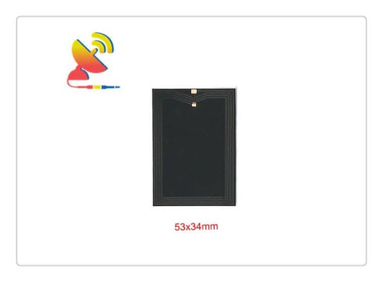
The RFID 13.56 MHz Near Field Communication Antenna CTRF-ANTENNA-FPC-1356-5334-NFC-ANT style is a Near Field RFID 13.56 MHz NFC Flex Antenna 53x34mm size 2dBi gain NFC Long-range Antenna supplied by the C&T RF Antennas Inc, China’s leading antenna manufacturer.
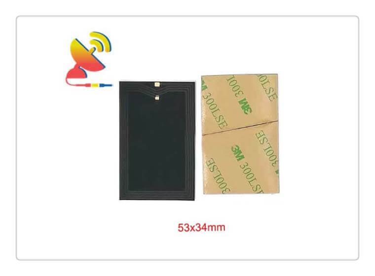
The RFID 13.56 MHz Near Field Communication Antenna is manufactured by C&T RF Antennas Inc, the NFC antenna manufacturer in China, we also provide other antenna types such as Through-hole Mount Antennas, Magnetic Mount Antennas, Rubber Duck Antennas, Fiberglass Antennas, PCB Antennas, FPC Antennas, Spring Coil Antennas, Sector Antenna, Yagi Antenna, etc.
C&T RF Antennas Inc provides the internal-external antenna with many antenna frequency bands such as Cellular, 6G, 5G, 4G, 3G, NB-IoT, GNSS, GPS, Dual-band Wifi, 5.8 GHz, 2.4 GHz, 169MHz, 230MHz, 315MHz, 433MHz, 868MHz, 915MHz LoRa, UWB, RFID, ADS-B, etc.
Contact us for more details on the RFID 13.56 MHz Near Field Communication Antenna such as the RFID 13.56 MHz Near Field Communication Antenna datasheet, RFID 13.56 MHz Near Field Communication Antenna pricing, and RFID 13.56 MHz Near Field Communication Antenna inventory, or other NFC Antenna styles.
RFID 13.56 MHz Near Field Communication Antenna Specifications
RFID 13.56 MHz Near Field Communication Antenna Electrical Specifications | |
| RF Antenna Type | 13.56MHz Antenna |
| Model | CTRF-ANTENNA-FPC-1356-5334-NFC-ANT |
| Frequency | 13.56MHz |
| Gain | 2dBi |
| VSWR | ≤1.8 |
| Impedance | 50 Ω |
| Polarization | Vertical Polarization |
| Cable Type | Null |
| Connector | Null |
| Cable Length | Null |
| Lightning Protection | DC-Ground |
RFID 13.56 MHz Near Field Communication Antenna Mechanical Specifications | |
| FPC Board Dimension | 53*34mm |
| Weight | Approx. 5g |
| Material | FPC Board |
| Operation Temperature | -40˚C ~ +85˚C |
| Storage Temperature | -40˚C ~ +80˚C |
| Color | Black |
| Antenna Design | Dipole Array |
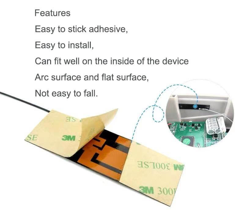
| Mounting | Self-Adhesive Type Mount |
| Safety Emission and other | RoHS Compliant |
| Applications | IoT/M2M, RFID |
The data transmission between the reader and the tag is carried out in the form of radio frequency signals (radio waves) through the air medium.
In order to achieve data transmission at high speed and over long distances, the data signal must be superimposed on a regularly varying signal relatively strong electric wave.
The rule change electric wave is called a carrier wave. The working frequency of the radio frequency recognition system is the carrier wave frequency. The carrier wave may be the sine wave or the square wave.
RFID system’s working mode
Full duplex (FDX)
Half-duplex (HDX)
The sequence of Time (SEQ)
Common encoding methods for RFID
Non-Return to Zero (NRZ, Non-Return to Zero): The binary numbers 0 and 1 are represented by Two levels to represent, commonly used -5 V means 1, +5 V means 0.
Manchester Code: 0 and 1 are represented by the change of voltage. It is specified that a jump occurs in the middle of each code element. A high jump represents 0 and a low jump represents 1. jump represents 1.
Differential Manchester coding: the jump still occurs in the middle of each code element, and the jump at the beginning of the code element is used A jump at the beginning of the code element is used to represent 0 and 1. A jump represents 0 and a no-hop represents 1.
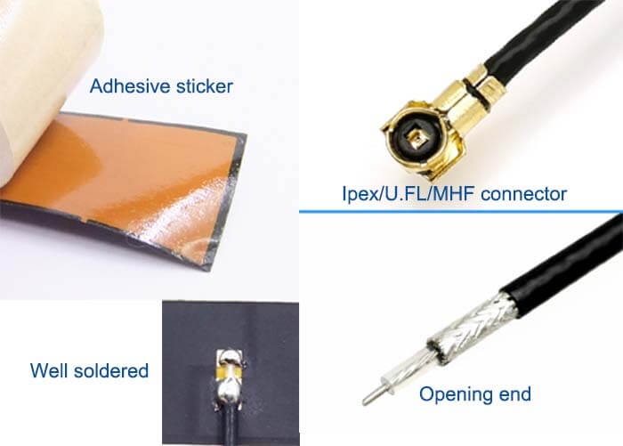
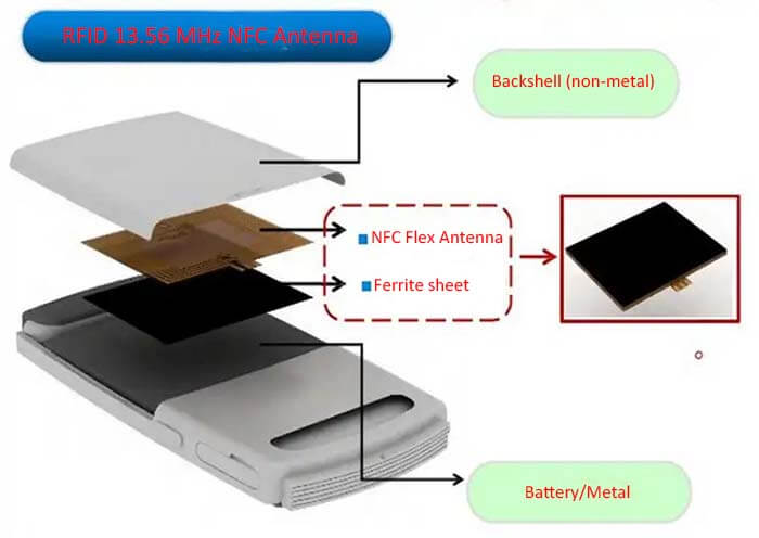
RFID 13.56 MHz Near Field Communication Antenna Features

Reviews
There are no reviews yet.