If you find that your newly purchased 2.4GHz or 5.8GHz wifi antenna router device does not provide the wireless coverage that you expected, it does not necessarily mean that there is a problem with the wifi antenna router device, or that you have placed the wifi antenna router device in the wrong location. More than 90% of the reason is that you did not configure a suitable wifi antenna to the router device.
Even if your Wi-Fi client can access the Internet through your home wireless router, have you checked the actual wireless signal strength, if the signal-to-noise ratio (SNR) is too low, the wireless transmission speed cannot reach 54Mbps or higher, of course, wireless Interference, etc. will also affect the transmission speed, but even the basic wireless signal is not good, so don’t expect high-speed Internet access.
Which type of wifi antenna should we choose? Choosing a suitable wifi antenna is actually a matter of knowledge. We must start by understanding the basic knowledge of the antenna. The principle of the antenna and some antenna parameters will be introduced below. I believe it can help you choose and install a suitable antenna. Thereby enhancing the effective coverage and performance of the wireless system.
The antenna is a passive body, that is, it does not need to provide power or other energy. It is also not a power amplifier and will not amplify the input wireless signal. On the contrary, due to the signal attenuation caused by the feeder and the connector, the wireless energy emitted will be greater than that of the input energy of the antenna contact is low.
The antenna only plays the role of a directional amplifier, so that the energy sent and received is concentrated in a certain area of the space, and the only purpose of the antenna is to change the energy distribution area to the place where it is needed.
If energy is delivered to places without wireless equipment, or if energy is excessively delivered to a certain area, it is wasteful. According to the law of invariance of energy, the energy delivered to one direction is strengthened and the energy in other areas is reduced.
Gain of wifi antenna
Gain is a general way of representing antenna characteristics. It refers to the strength gain in a certain area relative to the following two ideal standard transmission and reception modes. The ideal standard transmission and reception mode is that the energy of the radiator is emitted from an isotropic antenna (as shown in the figure below).
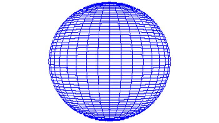
It is an isotropic radiator that emits in any direction in space, and all directions are 0dB. The gain unit calculated according to this standard as a reference is dBi. Another ideal standard transceiver mode is based on a free space half energy radiated by the wavelength dipole is used as a reference, and the calculated benefit unit is dBd.
Obviously, the latter’s radiator already has a gain relative to the former’s radiator. The calculated value is 2.16, that is, 1 dBd = 2.16 dBi. The antennas all use dBi as the calculation unit, and the typical gain of 2.4GHz or 5.8GHz ranges from 2 dBi to 26 dBi.
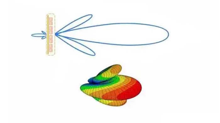
Radiation pattern of antenna
The gain can only be used as a reference for selecting the antenna. It can only display the gain in the direction of the strongest energy and does not provide any energy distribution. The radiation pattern can accurately display the energy distribution in the free space.
The commonly used is the horizontal radiation distribution. There are two types of the map (horizontal/azimuth sweep plane) and vertical radiation distribution map (vertical / elevaTIon sweep plane).
The figure below shows the horizontal and vertical radiation patterns of the 8dBi omnidirectional antenna produced by C&T RF Antennas Inc. The red line (H plane) is the horizontal distribution. If you look at the signal coverage from the top of the antenna, you will find 8dBi omnidirectional radiation.
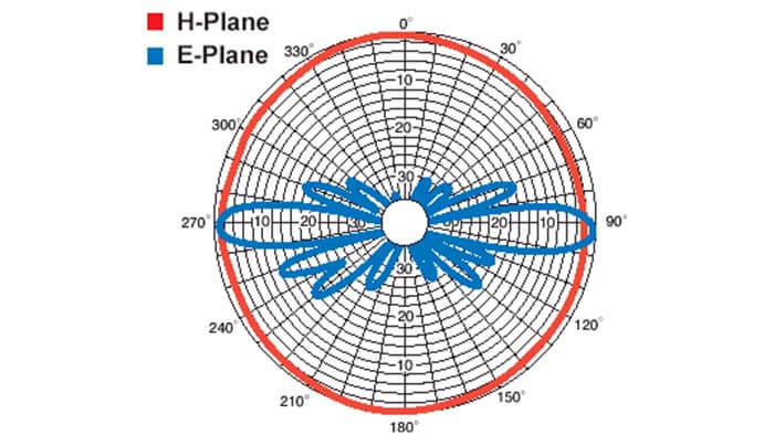
The energy of the booster antenna is distributed around 360 degrees with the antenna as the center; the blue line (E plane) is distributed vertically. I imagine you can see the signal coverage from the side of the antenna. The energy is only emitted at the same level, and the signal will not radiate to the sky or the ground.
Half power beamwidth
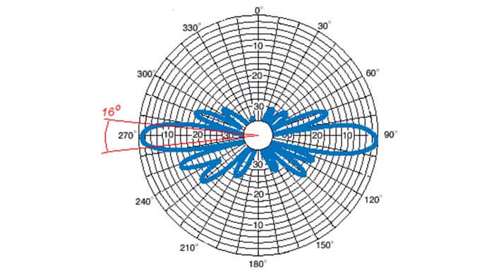
Since not all users can understand the radiation pattern, it is customary to use another simplified and effective parameter to describe the distribution of energy, this is the half-power beamwidth (3dB Beamwidth or half power Beamwidth), referred to as lobe Width, the calculation method is width between the two emission directions at half the highest power. We usually call this radiation the main beamwidth.
The beamwidth can be subdivided into horizontal and vertical. The figure below is calculated based on the figure above. The vertical beam width of the display angle is 16 degrees.
The gain is inversely proportional to the beamwidth. The lower the production of the horizontal beamwidth and the vertical beamwidth, the higher the antenna gain. The following table shows the maximum gain value of a typical antenna beamwidth.
Horizontal beamwidth (angle) | Vertical beamwidth (angle) | Maximum gain dBi |
360(omnidirectional) | 8 | 11.6 |
360(omnidirectional) | 15 | 8.8 |
150 | 15 | 12.6 |
150 | 30 | 9.6 |
120 | 30 | 10.6 |
120 | 60 | 7.6 |
90 | 15 | 14.9 |
90 | 30 | 11.9 |
60 | 30 | 13.6 |
60 | 60 | 10.6 |
Side lobes, back lobes, and front-to-rear ratio (F/B)
Side lobes, back lobes, and front-to-rear ratio (F/B) are another set of antenna parameters. Side/back lobes refer to less energy radiation other than the main wave, and their influence is waste energy.
Energy transfer to the side/back to interfere with other nearby receivers
The energy from other surrounding transmission devices may be introduced into the system through the back radiation tail receiving signal and become interference
The front-to-back ratio refers to the difference between the power at the peak of the radio wave and the power at a point 180° away from this point, typically 25 to 45 dB. A high front-to-back ratio can reduce interference to the coverage area of adjacent units.
Antenna polarization
Antenna polarization refers to the direction of the electric field vector in the radiated wave. Linear polarization refers to the portion of the energy in a certain plane (vertical, horizontal, or oblique with respect to the earth at a 45° angle), while circular polarization refers to the direction of the electric field vector in the radiated wave.
It is a circular rotation (LHCP on the left-hand side and RHCP on the right-hand side). In order to eliminate the loss caused by polarization mismatch, the receiving antenna must maintain the same polarization direction as the received radio signal.
Voltage standing wave ratio/VSWR
The voltage standing wave ratio (VSWR) of the antenna is the ratio of the reflected power to the input power, which is mainly affected by the matching degree between the input impedance of the antenna terminal and the characteristic impedance of the transmission line. The higher the matching, the finer the reflected wave and beam ratio will be reduced the energy transmitted to the antenna, thereby reducing the effective gain of the antenna.
The ideal ratio of the voltage standing wave ratio of the antenna is 1:1, that is, the input impedance is equal to the characteristic impedance of the transmission line, but it cannot be reached, typically 1.5:1 (96% power transmission).
The following table shows the voltage standing wave ratio and the reflected power relationship.
VSWR | Reflected power % | Transmission attenuation |
1:1 | 0.0 | 0.0 |
1.25:1 | 1.14 | 0.05 |
1.5:1 | 4.06 | 0.18 |
1.75:1 | 7.53 | 0.34 |
2:1 | 11.07 | 0.51 |
2.25:1 | 14.89 | 0.70 |
2.5:1 | 18.24 | 0.88 |
Wifi antenna categories
Wifi antennas can be divided into three categories according to the use situation, omnidirectional antennas with the main beamwidth horizontally emitted, omnidirectional antennas with the main beam downward, and directional antennas.
Omnidirectional antenna
An omnidirectional antenna means that the radiation is emitted in the same shape at 360 degrees horizontally. We must select the appropriate antenna according to the environmental needs, so that the most wireless devices can transmit wireless data under the required signal strength.
In a large-scale wireless network, choosing a suitable antenna and installation method can not only improve the overall coverage performance, but also reduce the number of APs to reduce costs.
Omnidirectional antenna with the main horizontal beamwidth
It can be connected to a wireless device or AP. If the AP and such omnidirectional antenna are installed in a very high place, such as a 30-meter-high lamp post outdoors since the antenna’s radiation shape is similar to a water bubble, most of the signals are radiated in the horizontal direction, and the radiation distance Increase, but it will cause a blind spot under the antenna. Therefore, the antennas of the transmitter and receiver must be at the same level.
In the warehouse, if the height of the floor is within ten meters, this type of omnidirectional antenna can also be used. Although part of the upward energy will be wasted, the main energy is radiated horizontally, so the coverage area will be larger than other antennas. Below the antenna, although it may not be within the lobe width, because it is not far from the antenna, the side lobes with less energy can already provide good signal coverage.
Omnidirectional antenna with main beam down
The radiation shape is similar to a hemisphere, the signal is emitted outwards and downwards at the same time, and only a small amount of energy is emitted upwards so that the wireless signal is evenly radiated and transmitted in the coverage area.
It is most suitable for installation in some high places above 20 meters, such as Coverage needs to take into account the same level and ground wireless equipment, this type of antenna is very ideal.
This type of antenna has a smaller horizontal coverage area than an omnidirectional antenna with a horizontal main beam, but the latter can only take into account wireless devices of the same level.
In some warehouses within ten meters of the floor, it is not recommended to use this type of antenna. Because excessive energy is emitted near the bottom of the antenna, which causes waste, we should switch to omnidirectional antennas with the main beam level to release the energy as much as possible of radiation in the horizontal direction to increase the coverage area.
Directional antenna
The radiated energy is only emitted in a certain direction of the antenna. There are different gains, horizontal beam widths, and vertical beam widths to choose from. It is suitable for environments where wireless devices are in a certain direction of the AP. It is also used in point-to-point and point-to-point applications multi-point wireless system.
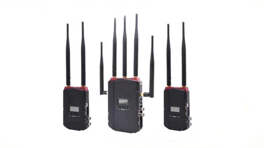
MIMO antenna
MIMO antennas are mainly used with wifi antenna 802.11n devices. Each transceiver component is equipped with more than one antenna (currently up to three) to increase the received signal and increase the transmission speed.
Based on multi-path reflection, the signal transmitted from one point reaches another receiving point with more than one receiving antenna. The direct signal and reflected signal received by different antennas may have different strengths and polarities to a certain extent, and the wireless components will be affected. Choose the best signal from them.
Except for the omnidirectional antennas with the main lobe horizontally emitted, the current MIMO antennas will have three antennas installed in the same component. Among the three antennas in the directional antenna, one of them will have a 90-degree different polarity from the other two.
You may also be interested in the below articles.