What is an Embedded PCB Antenna 2.4 GHz Wifi Antenna?
The Embedded PCB Antenna 2.4G antenna CTRF-ANTENNA-PCB-2450-4212-IPEX item is a high-performance internal antenna 2.4 GHz PCB Wifi antenna supplied by C&T RF Antennas Inc, an antenna manufacturer in China.
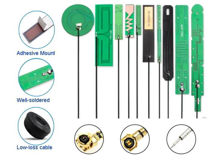
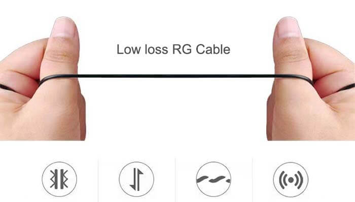
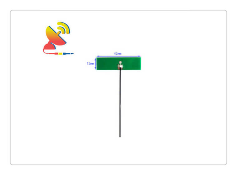
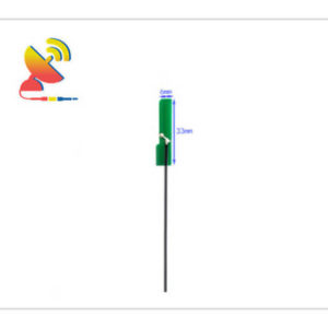
The Embedded PCB Antenna 2.4G wifi antenna comes with a 3dBi gain, Ipex connector, RG1.13 cable, 42x12mm PCB trace board, and dipole antenna design for Wifi, Bluetooth, Sigfox, Zigbee, etc.
The CTRF-ANTENNA-PCB-2450-4212-IPEX Embedded PCB Antenna 2.4G antenna can be used for the wifi, wireless, ISM, IoT, and M2M industries.
C&T RF Antennas Inc provides many 2.4GHz Wifi antenna types such as Through-hole Mount Antennas, Magnetic Mount Antennas, Rubber Duck Antennas, Fiberglass Antennas, PCB Antennas, FPC Antennas, Spring Coil Antennas, Sector Antenna, Yagi Antennas, etc.
We provide the RF antenna with many antenna frequency bands such as Cellular, 6G, 5G, 4G, 3G, NB-IoT, GNSS, GPS, Dual-band Wifi, 5.8 GHz, 2.4 GHz, 169MHz, 230MHz, 315MHz, 433MHz, 868MHz, 915MHz LoRa, UWB, RFID, ADS-B, etc.
C&T RF Antennas Inc provides RF wireless antennas for Wi-Fi And Bluetooth, GPS And GNSS, LoRa And ISM, IoT, And M2M applications.
Contact us for more 2.4 GHz PCB Wifi antenna details such as 2.4 GHz PCB Wifi antenna datasheet, 2.4 GHz PCB Wifi antenna pricing, and 2.4 GHz antenna inventory.
Or other 2.4 GHz antenna styles.
Embedded PCB Wifi Antenna 2.4G Antenna Specifications
Embedded PCB Wifi Antenna 2.4G Antenna Electrical Specifications | |
| RF Antenna Type | Embedded PCB Antenna |
| Model | CTRF-ANTENNA-PCB-2450-4212-IPEX |
| Frequency | 2400-2500 MHz |
| Gain | 3dBi |
| VSWR | ≤2.0 |
| Impedance | 50 Ω |
| Polarization | Vertical Polarization |
| Cable Type | RG1.13 |
| Connector | U.FL/IPEX |
| Cable Length | 100mm |
| Lightning Protection | DC-Ground |
Embedded PCB Wifi Antenna 2.4G Antenna Mechanical Specifications | |
| PCB Board Dimension | 42*12mm |
| Weight | Approx. 3g |
| Material | PCB |
| Operation Temperature | -40˚C ~ +85˚C |
| Storage Temperature | -40˚C ~ +80˚C |
| Color | Green |
| Antenna Design | Dipole Array |
| Mounting | Connector/Sticker |
| Safety Emission and other | RoHS Compliant |
| Applications | ISM/SCADA/Utilities, IoT/M2M, Wi-Fi/Bluetooth/Zigbee/Sigfox, etc |
Embedded Antenna Design
When integrating the antenna on the PCB, following the supplier’s requirements will enable the antenna to obtain the best performance.
The antenna is sensitive to the surrounding environment. Therefore, when there is an antenna on the PCB, the design layout should take into account the requirements of the antenna, because this may greatly affect the wireless performance of the device.
Care should be taken when integrating antennas into new designs. Even the material, number of layers, and thickness of the PCB will affect the performance of the antenna.
Position the antenna to improve performance
Antennas work in different modes and depending on the radiation pattern of a single antenna, they may need to be placed in a specific location, along the short side, long side, or corner of the PCB.
Usually, the corner of the PCB is the best place to place the antenna. This is because the corner position allows the antenna to have gaps in five spatial directions, and the feed of the antenna is located in the sixth direction.
Antenna manufacturers provide antenna design options suitable for different locations, so product designers can choose the antenna that best suits their layout.
Usually, the manufacturer’s datasheet will show a reference design, and if the reference design is followed, it will provide the best performance.
In such a design, when multiple antennas are used at the same time, the antennas are usually placed on different corners of the PCB.
Embedded PCB Antenna Design Features


Reviews
There are no reviews yet.