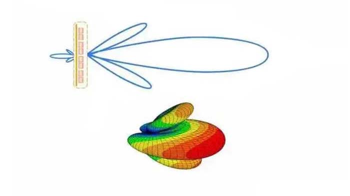
The 1/4 wave antenna is the simplest form of a vertical antenna. It provides good performance combined with an omnidirectional radiation pattern and simplicity of construction.
According to the theory of transmission lines, the 1/4-wavelength open circuit is equivalent to a series resonant circuit, so the entire load is purely resistive. On some occasions, due to environmental factors, the length of the antenna is often limited, so a loading antenna appears.
The 1/4 wave antenna's emission principle
The basic principle of antenna emission is: electricity travels in a conductor at a speed close to the light, and when it encounters a discontinuity in the conductor, it will be reflected back to the signal source. If the current is alternating, and the reflected current returns to the origin or feed point at the right time, the current will be strengthened by the following cycles, so that a small amount of energy is required to maintain the standing wave in the antenna.
The antenna is in resonance due to the presence of standing waves. Thereby launching radio waves into space. In the resonance state, the voltage is very small at the midpoint of the maximum current (the midpoint of the oscillator) but has a maximum value at both ends. Ohm’s law applies to the antenna. At the midpoint, the current is large and the voltage is low, so The resistance is small, and the situation at both ends is exactly the opposite, so the impedance is high.
Antenna and frequency (wavelength) relationship
The length of the antenna is determined according to the wavelength of the center operating frequency;
Wavelength and frequency are the inverse relationships, the calculation formula:
Wavelength (unit: meter)=300/frequency (unit: MHz)
When the center frequency is 150MHz, the wavelength is 2 meters, so the signal around 150MHz is called a 2-meter wave;
And the wavelength of 430MHz is 0.7 meters, so the signal around 430MHz is called a 70cm wave.
The length of the antenna is proportional to the wavelength, so it is inversely proportional to the frequency. The higher the frequency and the shorter the wavelength, the shorter the antenna can be.
The length of the antenna is not equal to one wavelength but is often 1/4 wavelength or 5/8 wavelength.
Why are 1/4 wave antennas commonly used?
Theory and practice have proved that when the length of the antenna is 1/4 of the wavelength of the radio signal, the transmission and reception conversion efficiency of the antenna is higher. Compared with half-wavelength and full-wavelength, the antenna size is much smaller. In contrast, the ratio of antenna transmission and reception efficiency to antenna size is the highest, so quarter-wavelength antennas are commonly used.
How to calculate 1/4 wave antenna?
1/4 wave antenna can be calculated by frequency, the formula is: antenna length (in meters) = (300/f)*0.25*0.96, f represents the frequency in MHz, 0.96 is the wavelength shortening rate (when electromagnetic waves propagate on the antenna, Some factors cause the wavelength to become shorter, that is, the shortening effect, which is generally considered to be shortened by about 5% in engineering).
According to this formula, you can easily calculate:
The quarter wavelength corresponding to VHF 144.00MHz is (300 / 144.00MHz) * 0.25 * 0.96 = 0.5 (m)
The quarter wavelength corresponding to UHF 435.00MHz is (300 / 435.00MHz) * 0.25 * 0.96 = 0.166 (m)
1/4 wave antenna application
In amateur radio, a quarter-wavelength antenna should be regarded as the simplest and not bad antenna, so it occupies a considerable proportion in the radio world.
For example, if you pay attention to police cars. Most of the antennas are quarter-wavelength antennas; like the 430MHz mobile phone you are using, most of its antennas are also quarter-wavelength antennas. Most of the big brother mobile phones are also 1/4-wavelength antennas. It can be seen that the 1/4-wavelength antenna definitely has its effect.
How to make a 1/4 wave antenna?
Take VHF (144MHz) as an example to make a 1/4 wave antenna
Prepare 5pcs 0.5-meter copper bars and an M-type socket joint connector (as shown in the picture).
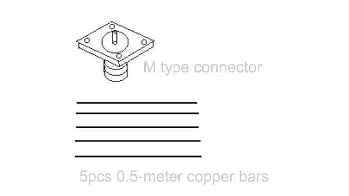
Then use a soldering iron to weld the M-shaped main shaft with one of the copper bars, then screw the other four on the four sides or solder them, and then lower each of the four to 45 degrees (Figure 2)
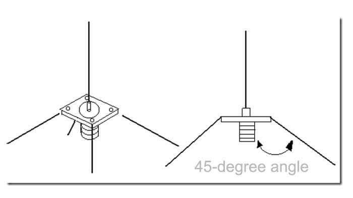
A ring is bent at the top of the main vibrator so that it can be easily hung outdoors or on the roof.
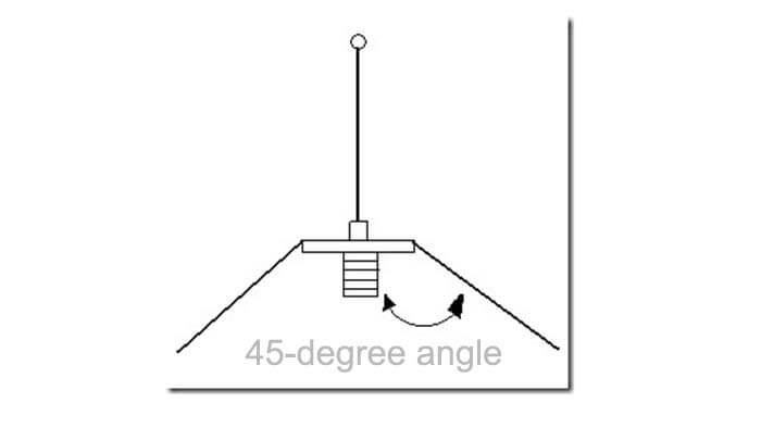
The one used above is an M-type female connector. Connect the M male connector to the feeder and screw it directly on the female connector, which is very convenient.
Using this method, we can make a variety of simple and small antennas, such as an FM antenna that works at 98Mhz.
The length of the sub is only 74cm, which is very lightweight. It is suitable for self-made by FM transmitter enthusiasts.
You may also be interested in the below articles.

