This article discusses the high-level design principles behind 5G antenna array architecture MIMO and beamforming technology to meet the requirements of 5G NR systems.
The higher the carrier frequency, the path loss will increase significantly relative to the fixed antenna size of the wavelength. A smaller antenna size at a higher carrier frequency means that more antennas are installed in the same area.
The path loss caused by the increase in carrier frequency can be overcome by using more antennas without increasing the overall physical size of the 5G antenna array.
In addition, when the carrier frequency increases above about 10 GHz, diffraction will no longer be the main propagation mechanism. Above 10Ghz, reflection and scattering will be the most important transmission mechanisms for non-line-of-sight transmission links.
Large-scale 5G antenna arrays are essential for NR systems to provide high coverage and high-capacity performance. Massive MIMO systems provide several benefits:
Enhanced coverage by using high-gain adaptive beamforming
Increase capacity by using high-order spatial multiplexing
The coverage enhancement capabilities of large-scale 5G antenna arrays are of great significance for alleviating the propagation challenges under high carrier frequencies. For interference-constrained systems operating in high-density deployments (for example, at lower carrier frequencies), capacity enhancement capabilities will be important.
In addition, MIMO technology can direct energy in the desired direction, and a narrow beamwidth can reduce interference in the system. Through the use of active antenna systems (AAS), better energy efficiency and better adaptability to business conditions can also be achieved.
The 5G antenna array architecture
For the next generation of wireless access, single-user, multi-user, and beamforming schemes are indispensable. Due to different carrier frequencies and deployment scenarios, different transmission and reception technologies can be used.
The all-digital baseband, hybrid array, and analog/RF array solutions described in Figure 1 and Figure 2 will be used in various ways by different implementations of base stations and UEs. Understanding the different candidate architectures is important for defining systems that are not related to the antenna array architecture.
As shown in Figure 1 and Figure 2, the difference between the three main array architectures is where the beamforming operations occur (such as the RF/analog domain and baseband/digital domain).
5G antenna array baseband architecture
In the baseband architecture of Figure 1, each antenna unit or antenna port has a transceiver unit, and the beamforming operation occurs in the baseband digital domain before up mixing to RF.
The baseband architecture provides a high degree of flexibility, such as frequency selective beamforming across OFDMA subcarriers, but at the cost of using a transceiver unit behind each antenna unit.
This architecture is the choice of LTE because the relationship between the number of antenna ports (for example, about 32 ports) and antenna cost is still manageable. However, one disadvantage of the baseband architecture is that it cannot scale in high carrier frequencies.
The use of large-scale antenna arrays in the cmWave or mmWave bands poses various challenges because the system bandwidth is very high and a large number of antenna elements are required to overcome the propagation challenges in these bands.
In a large-scale 5G antenna array, it becomes very difficult to use a separate transceiver behind each antenna unit, not only for cost reasons but also because broadband requires very high-speed A/D and D/A processors. In these processes, the device has significant power consumption requirements.
Simply extending the same MIMO baseband architecture to high-frequency bands is currently not economically feasible, considering that a considerable number of ports can be used, such as 256.
5G antenna array RF architecture
The alternative to the baseband architecture is a full radio frequency architecture, as shown in Figure 1, where the control of MIMO and beamforming is performed on the radio frequency in the analog domain, and the radio frequency components also have phase shift and potential gain adjustment capabilities.
Compared with the baseband architecture, frequency selective beamforming with an RF architecture is generally not feasible because the transmit weight is applied at the RF over the entire signal bandwidth.
Hybrid architecture
The middle ground between the digital architecture and the all-RF architecture is a hybrid architecture, where the control of MIMO and beamforming is separated between the RF and baseband.
Figure 2 shows two examples of hybrid architectures, where in addition to baseband MIMO precoding, multiple streams are beamformed at RF.
In a hybrid architecture, each RF beam is driven by a transceiver, and multi-stream beam weighting or precoding is applied to the input of the transceiver at the baseband.
The upper diagram of Figure 2-1 shows a hybrid architecture for a fully connected array configuration, where multiple RF beamforming weight vectors are applied in parallel to all antenna elements of the array.
In contrast, Figure 2-2 shows a hybrid architecture for a sub-array configuration, where each RF weight vector is applied to a unique subset of antenna elements. One advantage of the sub-array configuration is the lack of summing equipment behind the antenna element.
The hybrid architecture provides additional flexibility on the full RF architecture because the baseband transmitter part can adapt across the signal bandwidth to further optimize performance.
In addition, the ability to provide multi-beam transmission through baseband precoding is expected to improve capacity and coverage performance.
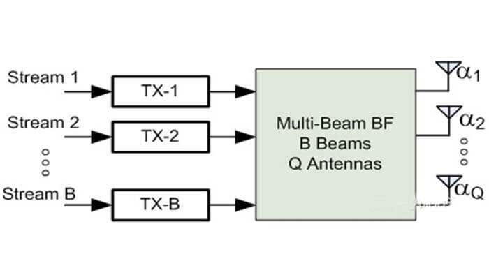
Figure 1-1 Baseband of 5g antenna array architecture

Figure 1-2 RF 5g antenna array architecture
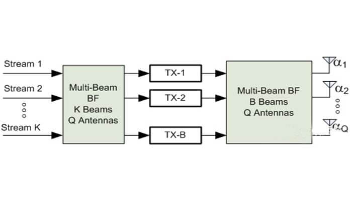
Figure 2-1 Fully connected mode of hybrid 5G antenna array architecture
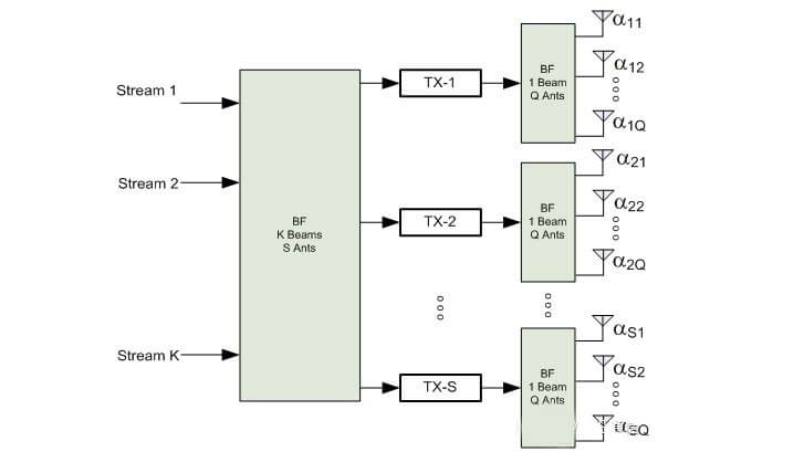
Figure 2-2 Sub-array mode of hybrid 5G antenna array architecture
From a standardization point of view, supporting different architectures does not necessarily require the use of any specific architecture in the actual implementation. The baseband architecture can support a hybrid architecture design method.
Of course, methods involving beams formed in the analog RF domain can also be implemented in the baseband digital domain, even though the actual implementation problems may be significantly different.
However, the method designed for digital architecture may not be able to be effectively or practically implemented through RF or hybrid architecture.
Recently, in LTE Rel-13 and Rel-14, a lot of work has been done to support larger antenna arrays and a higher number of antenna ports. The goal of FD-MIMO and eFD-MIMO work is to support up to 32 antenna ports of LTE Rel-13 and Rel-14.
For 5G NR systems, the FD-MIMO and eFD-MIMO mechanisms in Rel-13 and Rel-14 should be used as the starting point for MIMO and beamforming design. The focus is on mixing scenarios with severe coverage challenges and capacity challenges. The architecture’s large-scale 5G antenna array provides effective support.
Due to the challenge of supporting carrier frequencies up to 100Ghz, the support for SU/MU-MIMO and beamforming solutions should be fully scalable in terms of the number of antenna ports, the number of transceiver ports, the antenna array structure, and the number of physical antenna elements.
Antenna array implementation
When using frequency bands up to 100 GHz, how should the antenna array be designed?
Antenna array size
As the carrier frequency increases, the wavelength decreases, and the size of the antenna unit is usually proportional to the wavelength. As a result, as the carrier frequency increases, the number of antennas that can be placed in a given fixed area increases significantly.
From another perspective, as the carrier frequency increases, the size of the array with a fixed number of antenna elements is significantly reduced.
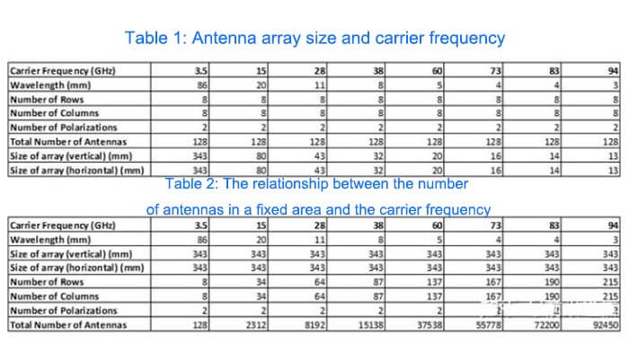
Table 1 below shows the size of an array with 8 rows, 8 columns, and 2 polarizations (assuming a two-dimensional array of cross-polarized elements is shared) as a function of frequency.
Table 2 below starts from the area required for the 128-antenna 2D array at 3.5 GHz and shows the number of antennas that can be placed in the area as a function of the carrier frequency.
5G antenna array configuration
The uniform rectangular panel array model involves the use of a single panel array composed of multiple sub-panels, where each sub-panel is a two-dimensional cross-polarized array.
This arrangement will generally include two transceiver units per sub-panel, and each transceiver unit will generally feed a beam that spans a common polarizing element within one sub-panel.
5G antenna array calibration
Generally speaking, beamforming schemes require some form of calibration to ensure a good beam pattern pointing in the desired direction. Due to the existence of vendor-specific calibration schemes, it may not be necessary to provide standardized support for 5G antenna array calibration.
If you have any antenna questions, please read our ANTENNA FAQ section, if you still cannot get the answer you need, please contact us.
You may also be interested in the below articles.