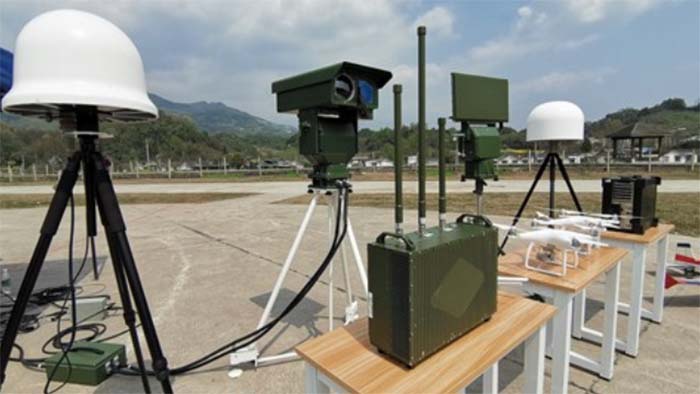
Antenna to transmit and receive wireless electromagnetic waves, how does transmitting and receiving antenna work?
Any radio frequency equipment cannot work without an antenna, which is responsible for transmitting and receiving electromagnetic radiation, or electromagnetic waves from the air.
In the transmitting direction, the antenna can convert the high-frequency current signal generated by the radio frequency equipment into electromagnetic waves, and transmit them into the air for propagation.
In the receiving direction, the antenna can capture electromagnetic waves in the air and convert the electromagnetic waves into high-frequency current signals inside the radio frequency equipment.
This article will disassemble the basic principles of electromagnetic waves, the basic principles of transmitting and receiving antennas, the transmission and reception of electromagnetic waves by wireless terminal equipment transmitting and receiving antennas, and common transmitting and receiving antenna parameters.
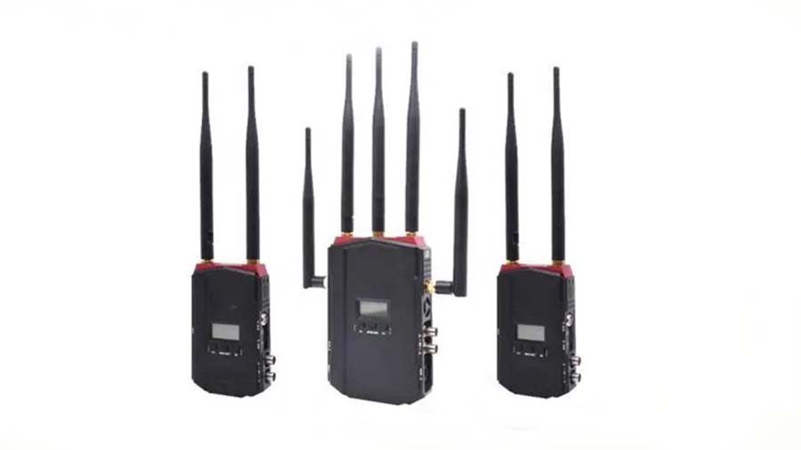
Wireless terminal data transmitting and receiving antenna working process
Wireless data transmission refers to the use of wireless data transmission modules to remotely transmit data output from industrial field equipment, or various physical quantities, which can be used for wireless analog quantity acquisition or wireless switching control.
If the transmission is a switching value, it can be remotely transmitted to equipment telemetry and remote control. Wireless data transmission can be divided into public network data transmission and private network data transmission.
Public network wireless transmission: GPRS, 2G, 3G, 4G, 5G, etc.
Private network wireless transmission: MDS digital radio, WiFi, ZigBee, etc.
Wireless data transmission equipment can be connected with data terminals such as PLC and RTU.
Transmitting
Signal transmitter: an electrical signal that generates a sine wave whose current or voltage intensity changes over time. The changing frequency is the frequency of the electromagnetic wave.
Induction coil: The generated periodically changing current signal is induced into the transmitting and receiving antenna loop, and the transmitting and receiving antenna loop generates an electrical signal within the same period.
Transmitting and receiving antenna: A periodically changing electrical signal. The electrical signal is sent to the air interface in the form of electromagnetic waves through the transmitting and receiving antenna.
Receiving
Transmitting and receiving antenna: The transmitting and receiving antenna can sense the electromagnetic field that changes in the air interface, and form a weak current that changes periodically in the transmitting and receiving antenna loop.
Induction coil: A weak current with a new period of induction is induced through the conjugate coil to a signal recovery and amplifying circuit.
Signal recovery circuit: The weak electrical signal with periodic changes induced by the signal recovery circuit is amplified and restored to the original periodic electrical signal.
The principles of electromagnetic induction
The changing magnetic field generates an electric field.
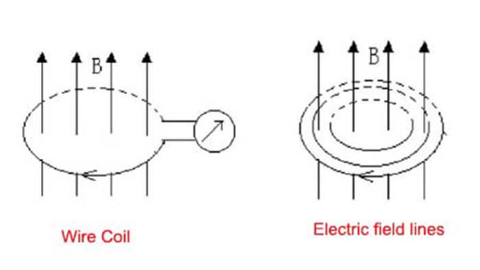
In the picture above, the direction of the magnetic field is perpendicular to the wire coil。
When the magnetic field is stable, no current can be generated in the conductive coil.
When the magnetic field undergoes a stable linear change, a current with constant current intensity will be produced in the conductive coil.
When the intensity of the magnetic field changes periodically, a current with periodic changes in current intensity will be generated in the conductive coil. The direction of current flow is the direction of the electric field.
The changing electric field generates a magnetic field.
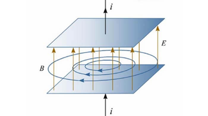
In the above figure, the direction of the magnetic field is perpendicular to the two electrode planes (capacitance)
When the electric field between the two electrode planes is stable, there is no magnetic field between the electrode planes, and the magnetic field strength is 0.
When the electric field between the two electrode planes undergoes a stable linear change, the magnetic field strength between the electrode planes remains stable.
When the electric field between the two electrode planes undergoes a stable periodic change, the electrode planes also follow the periodic change.
Electromagnetic field and electromagnetic wave
The changing electric field and the changing magnetic field are always accompanied and inseparable.
If in the physical space, a changing electric field will produce a changing magnetic field in the surrounding area, and the changing magnetic field will produce a changing electric field in the surrounding area. As a result, the electromagnetic field continuously expands and spreads in space, and every time it spreads, there is energy loss. This propagation process forms electromagnetic waves.
Wireless electromagnetic waves are a form of signal and energy propagation.
In the process of propagation, the changing electric field produces a changing magnetic field, and the changing magnetic field produces a changing electric field, which propagates alternately. In space, the electric field and the magnetic field are perpendicular to each other, and both are perpendicular to the direction of propagation.
How to convert the electrical signals of the electronic equipment into electromagnetic waves and send them into the air?
How do induce electromagnetic wave signals from the air and convert them into electrical signals of electronic equipment, that is, the reception of electromagnetic waves?
This work is done with a transmitting and receiving antenna!
Transmitting and receiving antenna
In a radio transceiver system, a device that radiates or receives wireless electromagnetic waves from space is a transmitting and receiving antenna.
The transmitting and receiving antenna is generally a section of the conductor exposed in the space.
The transmitting and receiving antenna working principle
A signal source at the transmitter
The first is the signal source of electronic equipment, which generates a changing current and changing voltage through a vibrating circuit.
The transmitting and receiving antenna transmits electromagnetic waves
The basic principle of changing the current signal and transmitting electromagnetic waves through the transmitting and receiving antenna is as follows.
The electromagnetic waves are bound in parallel cables. If the cables are opened at a certain angle, the electromagnetic waves will be strengthened. If the two cables are completely straightened, the electromagnetic waves cannot return from one wire to the other wire and have to go out and spread.
The two wires that generate electromagnetic waves are called vibrators.
Under normal circumstances, the size of the vibrator should be >= half a wavelength. At this time, the transmission effect is good, so it is often called a half-wave vibrator.
An antenna with a length of λ/2 is also called a dipole antenna. Even means an even number, also means 2, and the pole is the guideline. A dipole is an antenna that requires 2 wires.
With the vibrator, electromagnetic waves can be emitted continuously.
1/4 wavelength vibrator 1/4 wave antenna
A half-wave oscillator requires two poles to be an antenna. In ordinary consumer electronic equipment, a single pole antenna is common. In a printed circuit board or antenna module, the conductor length used as an antenna is only λ/4, which has the same performance. Such an antenna is called a quarter-wave antenna or 1/4 wave antenna.
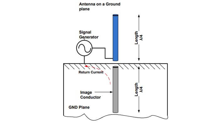
In the above figure, by placing a ground plane at a certain distance below the antenna wire, a wire with the same length (λ/4) as the antenna can be created.
When combined, the ground pins on these PCB boards or chips are used as dipole antennas.
This type of antenna is called a quarter-wavelength (λ/4) antenna 1/4 wave antenna.
Almost all transmitting and receiving antennas on the PCB are implemented in the size of a quarter wavelength on the copper ground plane.
Please note that the signal is now single-ended and the ground plane can also be used as a return path.
The transmitting and receiving antenna receives electromagnetic waves
Receiving is just the reverse process of transmitting, which is also done through the transmitting and receiving antenna.
The transmitting and receiving antennas can sense the changes in the electromagnetic field in the physical space and convert it into the changing current in the wire. This is the reception of electromagnetic waves. The ammeter can display the magnitude of the current in the wire.
There is a question here. There are many electromagnetic waves of different frequencies in space. Does it mean that the transmitting and receiving antennas can receive electromagnetic waves of all frequencies?
The length of the transmitting and receiving antenna is also involved here.
In general, the receiving effect is good when the size of the vibrator is >= half a wavelength.
When the transmitting and receiving antenna length has been determined, electromagnetic signals with a wavelength greater than twice the antenna length cannot be effectively received by the transmitting and receiving antenna. In other words, it is filtered out by the transmitting and receiving antenna.
When the length of the transmitting and receiving antenna has been determined, can electromagnetic signals with a wavelength of <=2 times the length of the antenna be effectively received by the transmitting and receiving antenna?
The answer is yes.
However, not all electromagnetic waves of wavelengths or frequencies are required by electronic devices, and redundant electromagnetic signals become interference signals.
How to receive only the signals of the required frequency or wavelength?
This requires another device: a filter
Filter to filter electromagnetic waves in a specific frequency range
What is fliter?
The filter is a filter circuit composed of capacitors, inductors, and resistors. The filter can effectively filter out the frequency point of a specific frequency in the power line or the frequency other than the frequency point to obtain a power signal of a specific frequency, or eliminate a power signal of a specific frequency.
Filter classifications
According to the frequency band of the passed signal, it is divided into five types: low-pass, high-pass, band-pass, band-stop, and all-pass filters.
Low-pass filter:
It allows low-frequency or DC components in the signal to pass, and suppresses high-frequency components or interference and noise;
High-pass filter:
It allows the high-frequency components in the signal to pass and suppresses low-frequency or DC components;
Bandpass filter:
It allows signals in a certain frequency band to pass, and suppresses signals, interference, and noise below or above the frequency band;
Band rejection filter:
It suppresses the signal in a certain frequency band and allows the signal outside the frequency band to pass, also known as the notch filter
The effects of different filters are explained below.
Low pass filter:
From 0 to f2 frequency, the amplitude-frequency characteristic is flat, it can make the frequency components lower than f2 in the signal pass almost without attenuation, and the frequency components higher than f2 are greatly attenuated or filtered out.
High pass filter:
Contrary to low-pass filtering, from frequency f1 to ∞, its amplitude-frequency characteristics are flat. It makes the frequency components higher than f1 in the signal pass almost without attenuation, while the frequency components lower than f1 will be greatly attenuated.
Bandpass filter:
Its passband is between f1 and f2. It allows the frequency components higher than f1 and lower than f2 in the signal to pass through without attenuation, while other components are attenuated or filtered out.
Bandstop filter:
Contrary to bandpass filtering, the stopband is between frequencies f1 to f2. It makes the frequency components higher than f1 and lower than f2 in the signal attenuated, and the signals of the remaining frequency components pass almost without attenuation.
In short, with the existence of the filter, the receiving device does not need to worry, the antenna can receive excess high-frequency electromagnetic waves with a wavelength <=2 times the length of the antenna element.
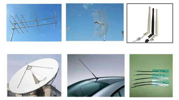
Types of wireless terminal transmitting and receiving antennas
Cable antenna
This is a section of cable that extends into the free space on the PCB. Its length is λ/4 and is placed on the ground plane. ie, PCB antenna, FPC antenna, pigtail wifi antenna, etc.
This transmitting and receiving antenna is powered by a 50-Ω4 impedance transmission cable.
Generally, due to the size and three-dimensional exposure, the wire antenna provides the best performance and radiation range.
The cable can be straight, spiral, or looped. It is a three-dimensional (3D) structure in which the transmitting and receiving antenna is 4-5mm higher than the PCB and extends into space.
PCB antenna
It is a PCB trace antenna on the PCB board, and it can be drawn as a straight trace, an inverted F-shaped trace, a serpentine or circular trace, or a swing curve based on transmitting and receiving antenna type and space constraints.
In a PCB antenna, the antenna becomes a two-dimensional (2D) structure on the same plane of the PCB; see the figure below.
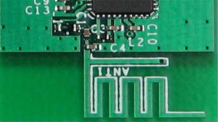
When a 3D antenna exposed to space is placed on the PCB layer as a 2D PCB trace, certain guidelines must be followed. In general, compared with wire antennas, it requires more PCB space, low efficiency, but low cost, easy to manufacture, and can provide an acceptable wireless distance for BLE applications.
Chip antenna / module antenna
This is an antenna with a conductor. The antenna and conductor are assembled in a small IC package. This is useful when the printed circuit board PCB antenna has limited space or supports 3D wire antennas.
Transmitting and receiving antenna radiation pattern
The transmitting and receiving antenna pattern is also called the radiation pattern. The energy pattern is a visual representation that describes the distribution of energy in different directions (not different physical distances) at a certain physical space point in the space of the antenna accessory. The keyword here is “direction”, and the variable parameter is direction, not distance.
The transmitting and receiving antenna radiation pattern is a graph that characterizes the relationship between the antenna’s radiation characteristics (field strength amplitude, phase, polarization) and the spatial angle or direction.
The complete radiation pattern is a three-dimensional space figure, which is drawn by measuring the radiation characteristics point by point on a spherical surface with a sufficiently large radius r with the transmitting and receiving antenna phase center as the sphere center (coordinate origin).
According to the radiation characteristics of the measured electromagnetic waves, the radiation pattern is divided into:
Field strength pattern: the measured characteristic is the field strength in different directions
Power pattern: the measured characteristic is power in different directions
Polarization pattern: the measured characteristic is the polarity in different directions
Phase pattern: the measured characteristic is the phase in different directions
The surveying and mapping of the three-dimensional spatial pattern are very troublesome. In actual work, it is generally only necessary to measure the pattern of the horizontal plane and the vertical plane (that is, the XY plane and the XZ plane), which becomes the horizontal pattern and the vertical pattern.
Regarding the characteristics of the magnetic field, if no additional explanation is given, the conventional pattern usually refers to the pattern of the field strength amplitude, rather than the pattern of other characteristics.
The transmitting and receiving antenna radiation pattern can be drawn in polar coordinates or rectangular coordinates.
The characteristics of the polar coordinate pattern are intuitive and simple, and the distribution characteristics of the transmitting and receiving antenna radiation field strength in different directions can be directly seen from the pattern.
A direction map is drawn by rectangular coordinates, the abscissa represents the direction angle, and the ordinate represents the intensity of this direction.
The following figure shows two coordinate representations of the pattern of the same transmitting and receiving antenna and the same position.
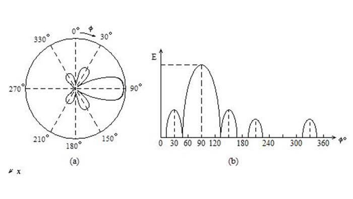
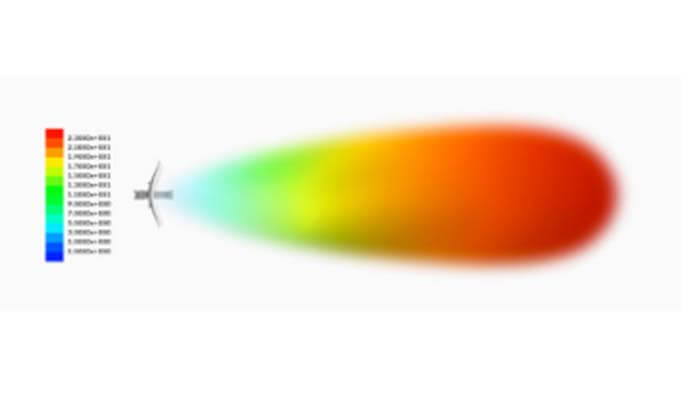
The transmitting and receiving antenna radiation pattern is an important figure to measure the performance of the antenna. You can observe the various parameters of the antenna from the antenna radiation pattern. The following is an example of the petal radiation pattern.
In the directional diagram, the petal-shaped places are places with electromagnetic wave energy, and the other places are places without electromagnetic wave coverage.
The farther the distance from the origin, the stronger the electromagnetic field energy in this direction (not this physical space point). That is, the radius of the circle represents the maximum field strength in a certain direction.
The stronger the field strength, the farther the electromagnetic wave travels in this direction.
Omnidirectional antenna and directional antenna
Omnidirectional antenna
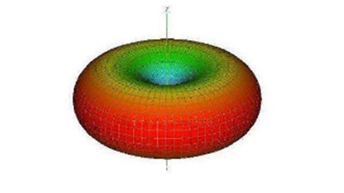
The figure above is the three-dimensional energy/field intensity pattern of the omnidirectional transmitting and receiving antenna. The center is the location of the antenna.
In the horizontal pattern, it shows uniform radiation at 360°, which is usually said to be non-directional.
In the vertical pattern, it is shown as the thickness of the pattern, that is, a beam with a certain width. In general, the smaller the beamwidth is, the greater the gain.
The omnidirectional antenna is generally used in the station type of the suburban district system in the mobile communication system, and its coverage is large.
The above picture also shows a magical phenomenon, that is, directly above and below the antenna, although it is very close to the antenna, there is no electromagnetic wave energy coverage. The receiving terminal cannot receive the electromagnetic wave signal transmitted by the antenna at this position.
Generally, the transmitting and receiving antenna of the wireless terminal is an omnidirectional antenna, and the pattern of the transmitted electromagnetic wave is also the radiation pattern of the omnidirectional antenna.
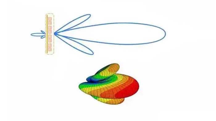
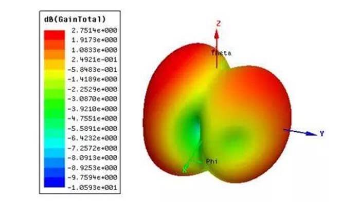
Directional antenna
On the horizontal pattern, it shows the energy radiation of a certain angle range, which is usually said to be directional.
Like the omnidirectional antenna in the vertical direction, it appears as a beam with a certain width in the pattern. The smaller the beamwidth is, the greater the gain.
Directional antennas are generally used in communication systems where the communication distance is long, the coverage area is small, the target density is high, and the frequency utilization rate is high.
Other forms of radiation patterns: three-dimensional radiation patterns, plane radiation pattern
The above-mentioned directional diagrams, especially the horizontal and vertical directional diagrams, all refer to the horizontal and vertical directions. It is assumed that the direction of the electric or magnetic field is horizontal or vertical.
In fact, the direction of the electromagnetic wave, electric field, or magnetic field emitted by the transmitting and receiving antenna is not necessarily vertical or horizontal, depending on the design of the antenna itself and the location of the antenna.
The characteristic that describes the direction of an antenna’s electric or magnetic field is the polarization of the transmitting and receiving antenna.
Transmitting and receiving antenna polarization
The transmitting and receiving antenna polarization is a parameter that describes the spatial orientation of the electric or magnetic field of the electromagnetic wave radiated by the antenna. It can be divided into horizontal polarization, vertical polarization, etc.
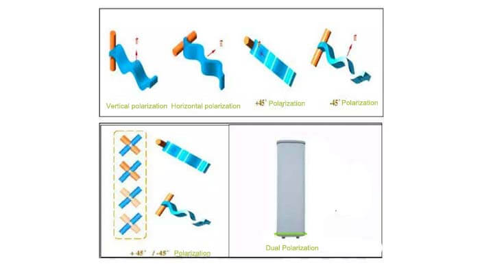
Horizontal polarization: The electromagnetic wave transmitted by the transmitting and receiving antenna is diffused in the horizontal direction, not in the vertical direction.
Vertical polarization: The electromagnetic wave transmitted by the transmitting and receiving antenna is diffused in the vertical direction, not in the horizontal direction.
The polarization of the transmitting and receiving antenna depends on:
(1) The characteristics of the transmitting and receiving antenna itself
(2) Transmitting and receiving antenna installation method
(3) Number of transmitting and receiving antennas
Common transmitting and receiving antenna parameters
Radiation pattern (width of main beam)
It reflects the concentration of electromagnetic wave energy in the main direction. The larger the area (two-dimensional) or volume (three-dimensional) of the main beam accounts for the total area or volume, the more concentrated the electromagnetic waves transmitted by the antenna are in the main direction.
Transmitting and receiving antenna gain
This is one of the most common parameters.
The transmitting and receiving antenna gain, under the condition of equal input power, the ratio of the power density of the signal generated by the actual antenna, and the ideal radiating element at the same point in space.
The gain usually refers to the ratio of the maximum power in the transmitting and receiving antenna’s maximum radiation direction (main beam direction) to the power of the omnidirectional antenna in this direction.
It quantitatively describes the degree to which an antenna concentrates the input power and radiates it.
The gain obviously has a close relationship with the antenna radiation pattern. The narrower the main beamwidth of the radiation pattern, and the smaller the side beamwidth is, the higher the gain. Transmitting and receiving antenna gain is used to measure the ability of an antenna to send and receive signals in a specific direction. It is one of the most important parameters for selecting a base station antenna.
The increase in gain mainly depends on reducing the beam width of the radiation on the vertical plane, while maintaining the omnidirectional radiation performance on the horizontal plane.
Increasing the gain can increase the coverage of the network in a certain direction, or increase the gain margin within a certain range.
The parameters representing the antenna gain are dBd and dBi.
dBi is the gain relative to the point source antenna, and the radiation in all directions is uniform;
P2: The energy or power of the actual antenna at this point.
P1: The energy or power of the theoretical omnidirectional antenna at this point.
The gain of dBd relative to the symmetrical array antenna is dBi=dBd+2.15.
Under the same conditions, the higher the gain, the farther the radio wave travels.
The gain of the directional antenna of the GSM base station is 18dBi, and the gain of the omnidirectional antenna is 0dBi.
Standing wave ratio (VSWR) / Return loss (RL) / S11
RL=10lg (incident power/reflected power)
Standing wave ratio VSWR=(1+ reflection coefficient)/ (1- reflection coefficient)
RL=-S11
The value of return loss is between 0dB and infinity. The smaller the return loss is, the worse the matching; the larger the return loss is, the better the matching. 0 means total reflection and infinity means perfect match.
It can also be seen that the range of VSWR=1~∞, and the larger the value of VSWR, it means that the connection at the joint is not good.
Transmitting and receiving antenna frequency Range
The length of the transmitting and receiving antenna determines the frequency range of the electromagnetic wave received by the antenna.
The longer the length of the transmitting and receiving antenna is, the lower and the lowest frequency of electromagnetic waves that can be received.
The shorter the length of the transmitting and receiving antenna, the higher the lowest frequency of electromagnetic waves that can be received.
If you have any transmitting and receiving antenna question, please read our ANTENNA FAQ section, if you still cannot get the answer you need, please contact us.
You may also be interested in the below articles.